Turbomachinery and Airfoil Demonstration Cases
Official preprint:10.5281/zenodo.18932808
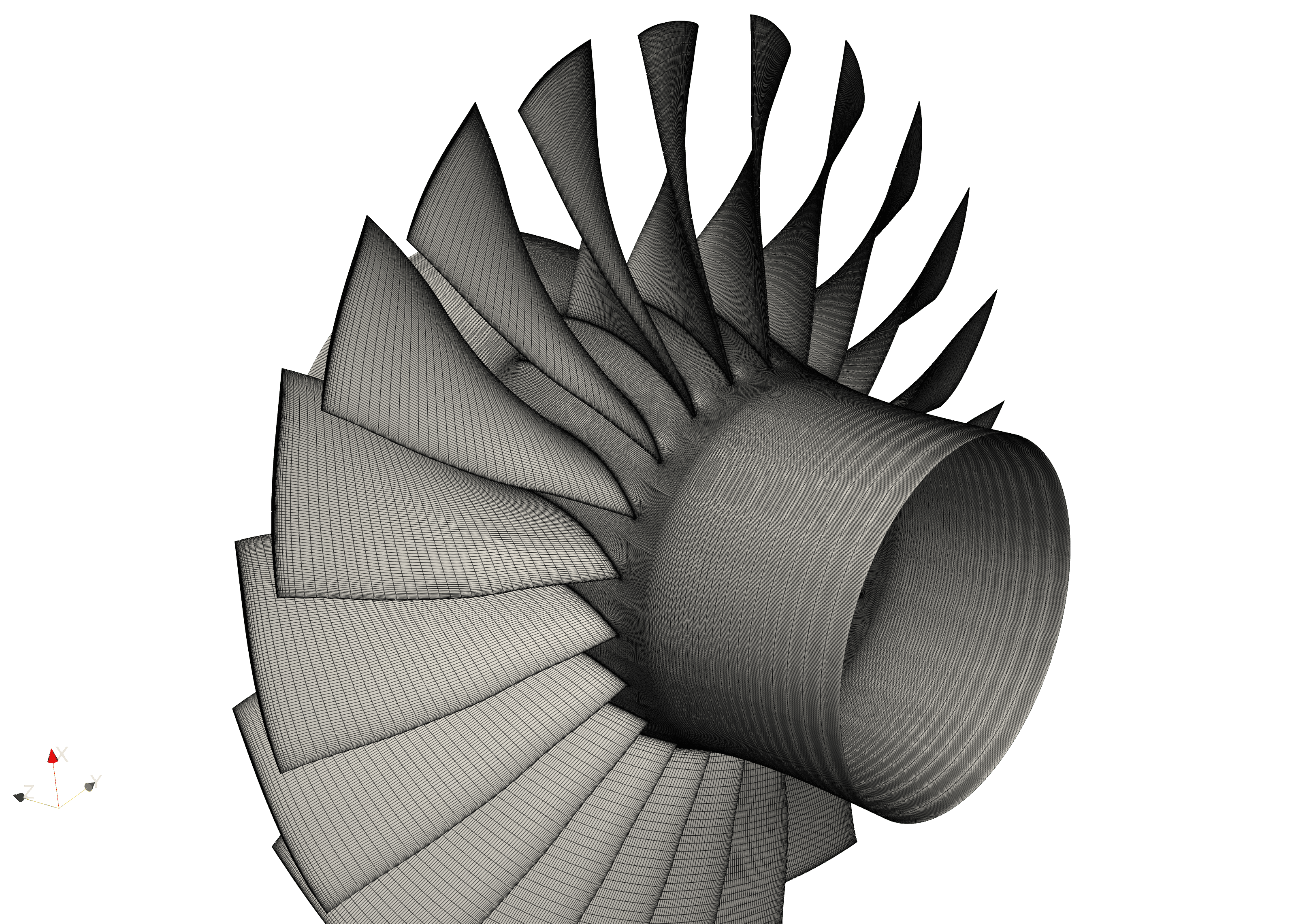
In the design and optimization of turbomachinery, Computational Fluid Dynamics (CFD) simulation plays a crucial role, and mesh generation, as the foundation of CFD simulation, directly determines the accuracy and reliability of simulation results. Therefore, to comprehensively validate and evaluate the performance of our mesh generation tool in the aerospace and turbomachinery fields, while considering the level of detail and open-source availability of data, we selected Rotor37, Rotor67, T106A/C, and VKI LS89 as core test cases. These cases have been widely adopted as industry-standard benchmarks not only because they cover various typical turbomachinery types and complex operating conditions ranging from transonic compressors to low-pressure turbine cascades and high-pressure turbine blades, but more importantly because they encompass complex flow phenomena that pose severe challenges to mesh quality, such as shock waves, separation, transition, tip leakage flow, and secondary flows. Additionally, these cases all have detailed and publicly available experimental data from authoritative institutions such as NASA and VKI, providing indispensable and reliable references for accurately evaluating mesh generation quality and validating CFD simulation results.
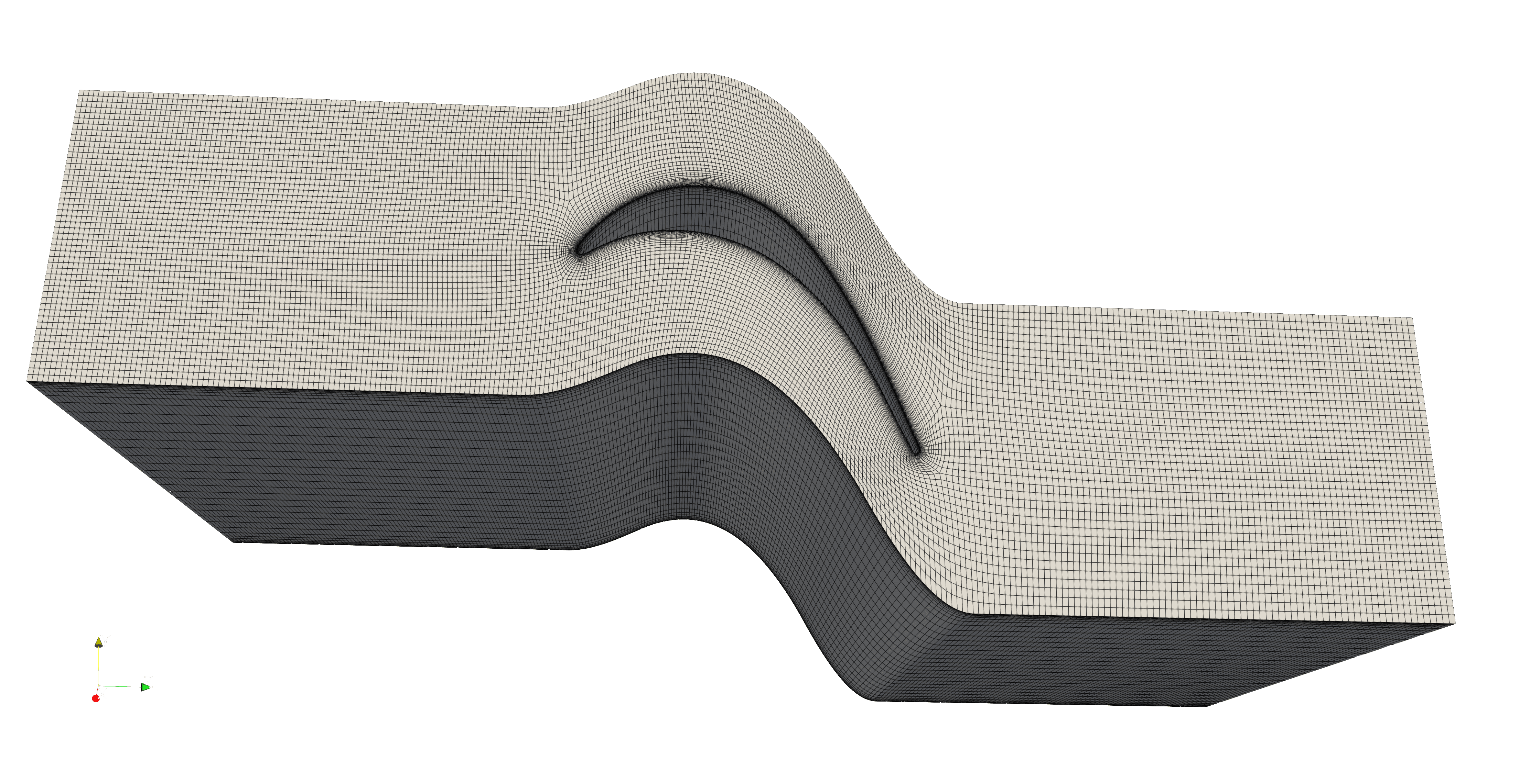
T106A
Case Introduction:
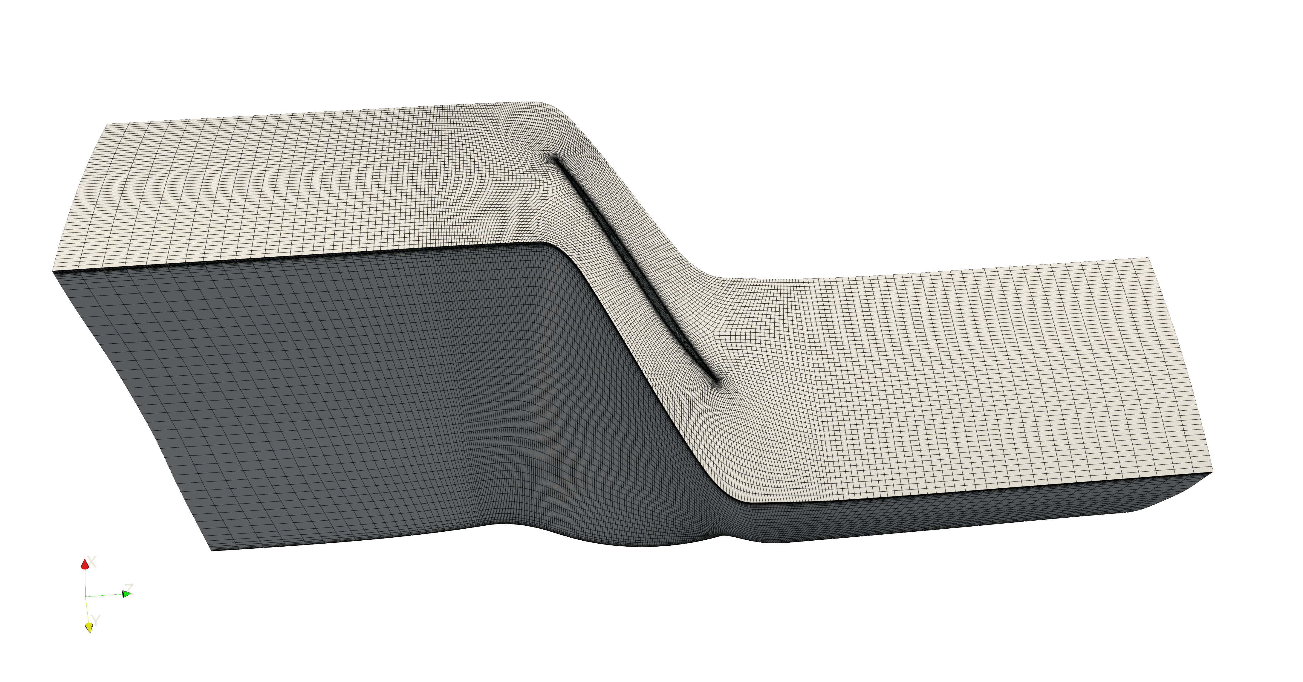
The T106 airfoil is a representative design of the mid-span section of the rotor blade from the Pratt & Whitney PW2037 engine, which was an optional powerplant for the Boeing 757 aircraft. The modern aero-engine design trend is to reduce the number of low-pressure turbine blades to decrease weight and manufacturing costs. This means each blade needs to withstand higher aerodynamic loads, leading to the development of "ultra-high-lift" airfoils like the T106, characterized by higher velocity peaks on the suction surface followed by significant diffusion, which makes boundary layer separation and transition phenomena more prominent.
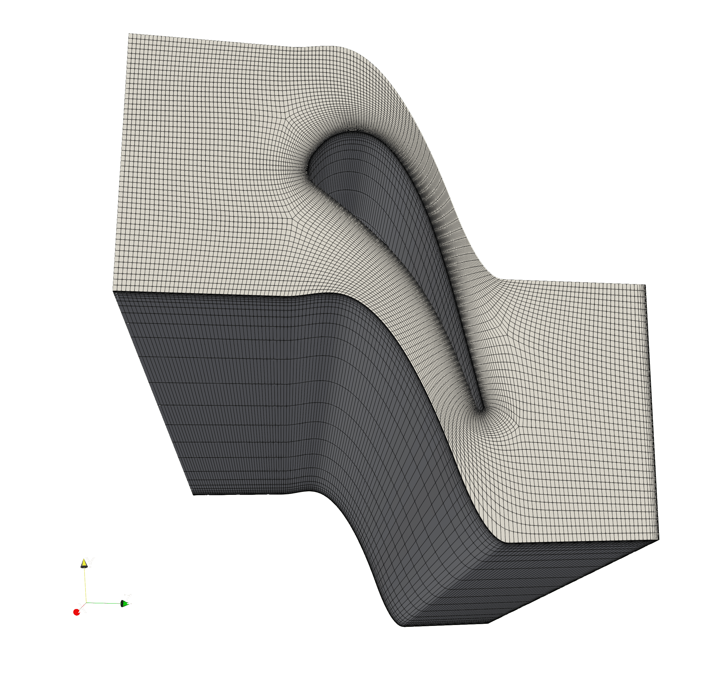
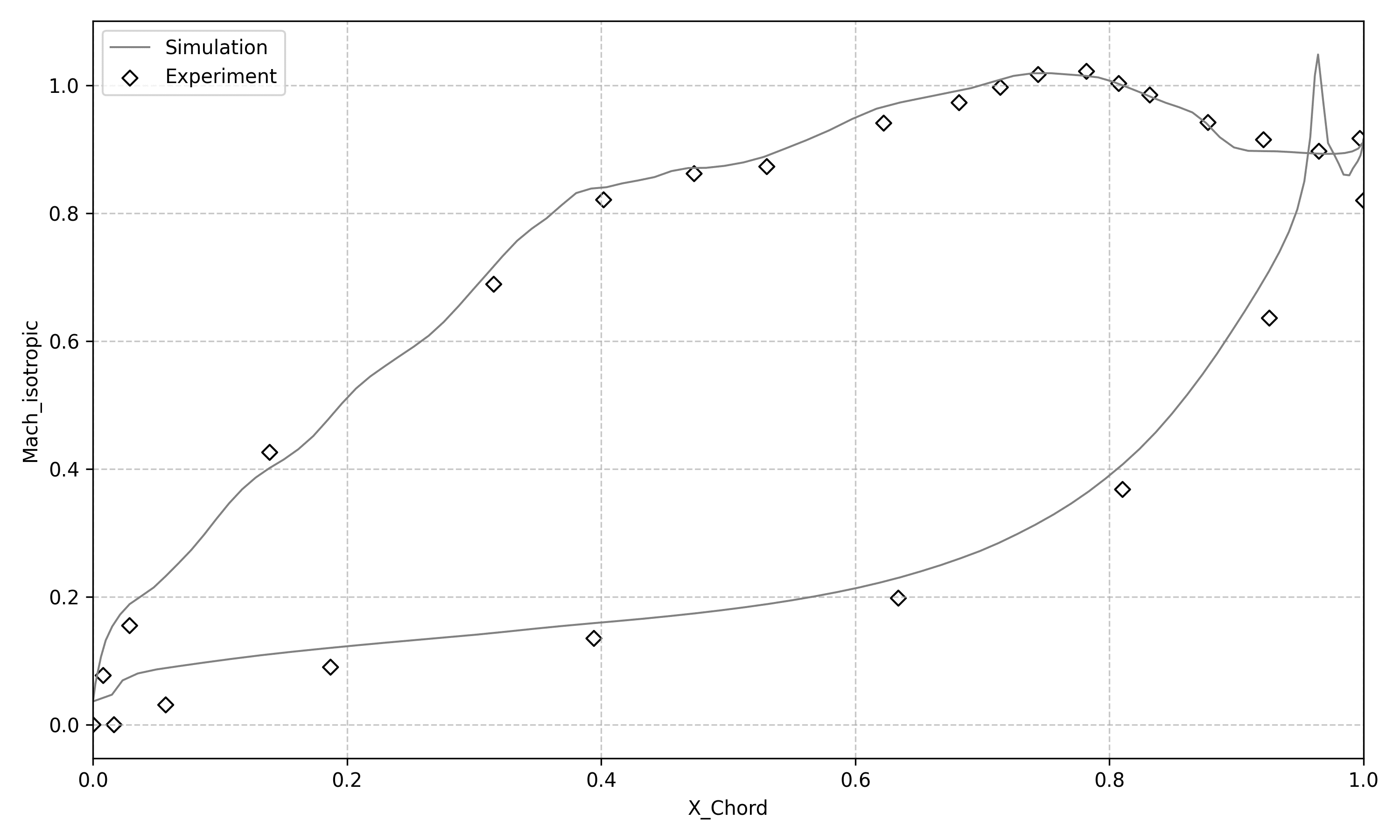
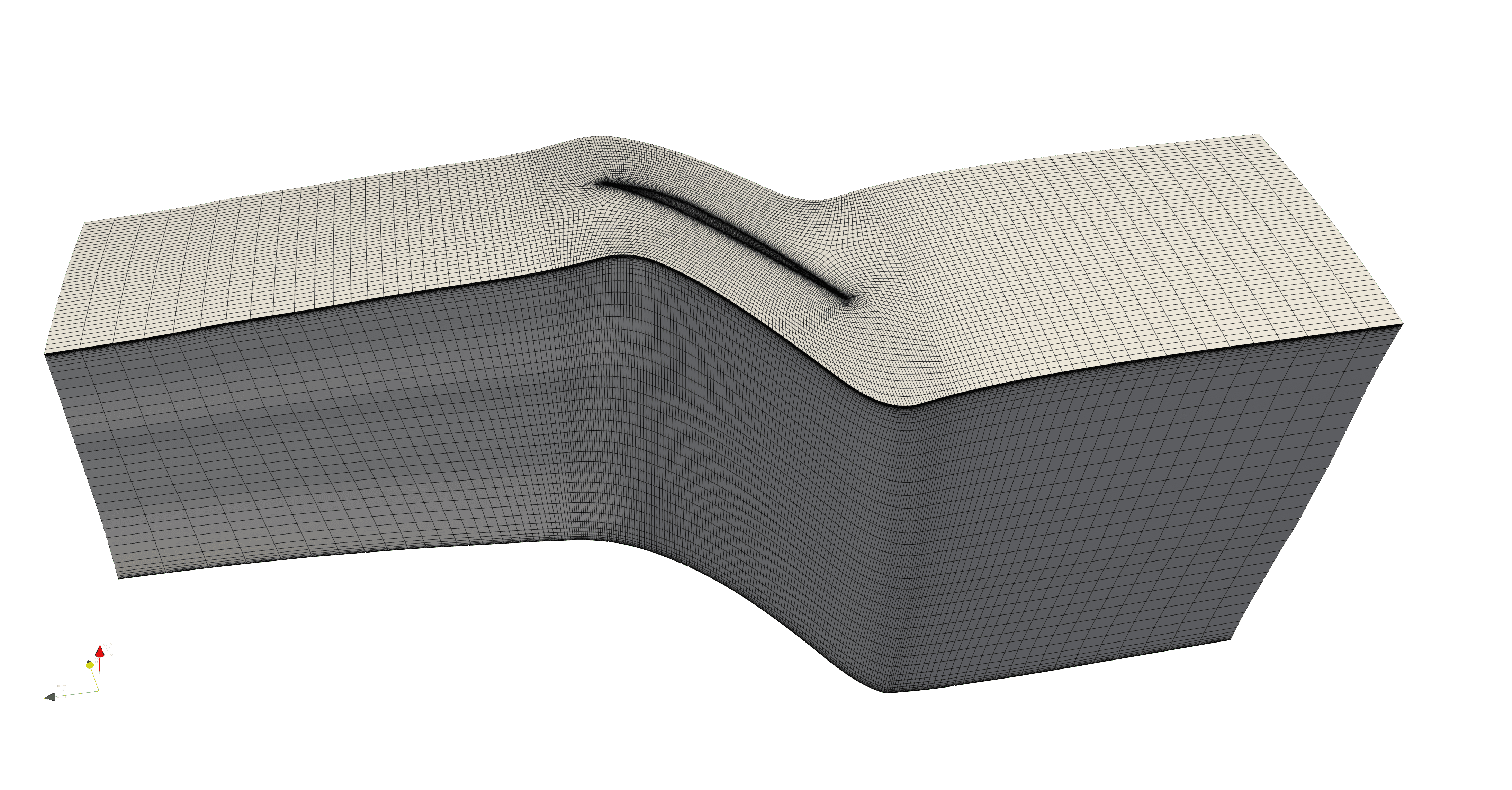
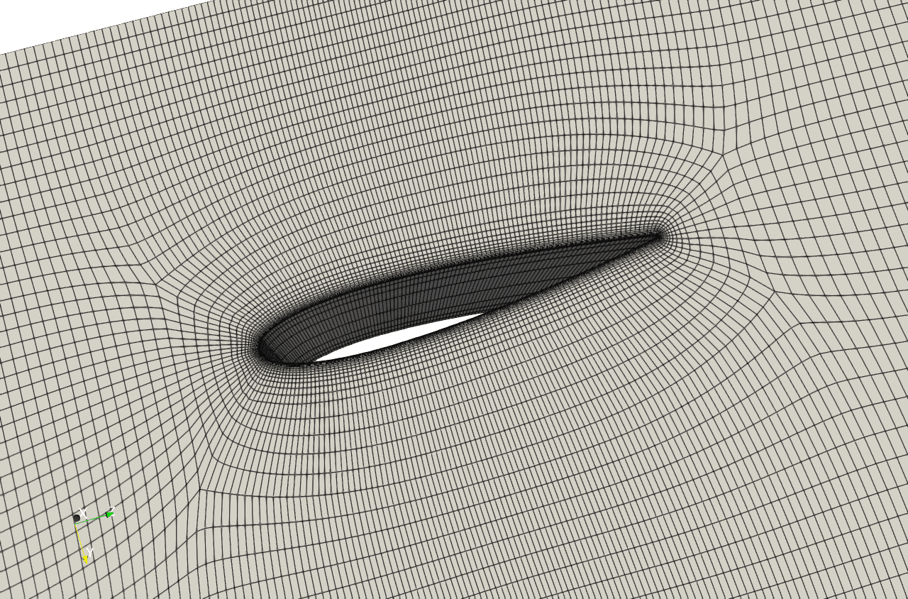
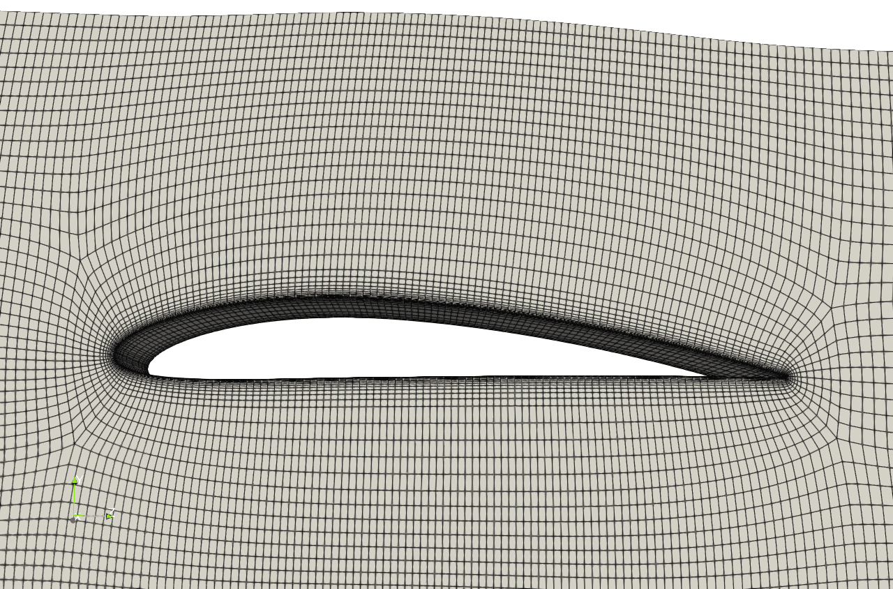
T106A and T106C are both classic low-pressure turbine cascades, representing lightly-loaded and heavily-loaded operating conditions respectively (the T106A experiments also considered the effects of upstream and downstream wakes). Flow in low-pressure turbines is typically characterized by low Reynolds numbers, high angles of attack, and is often accompanied by laminar separation and transition phenomena. The distinctive feature of these two cascades is that their suction surfaces are prone to flow separation and laminar-to-turbulent transition. Accurately capturing these phenomena requires high-precision meshes to resolve the boundary layer, especially in separation and reattachment regions.
Numerous laboratories have conducted detailed experimental tests on the T106 series cascades under various operating conditions, including the von Kármán Institute for Fluid Dynamics (VKI), the University of the Bundeswehr Munich, and the Whittle Laboratory at Cambridge University.
Data Source: Peter Stadtmüller, Leonhard Fottner, Andreas Fiala, EXPERIMENTAL AND NUMERICAL INVESTIGATION OF WAKE-INDUCED TRANSITION ON A HIGHLY LOADED LP TURBINE AT LOW REYNOLDS NUMBERS, ASME Turbo Expo 2000: Power for Land, Sea, and Air, 10.1115/2000-GT-0269
Mesh Generation Configuration: The Case_T106A.json used for computation is as follows
{
    "mesh": {
        "scale_factor":0.505,//Coordinate scaling factor
        "cor_fac":1,//Overall coarsening factor for non-O-type mesh
        "refine_fac":1,//Overall mesh refinement factor
        "ywall":1.0e-5,
        "zwall":1.0e-4,
        "aspect_ratio":800.0,
        "outlet_refine":false
    },
    "mode": {
        "geometry":"blade",//Blade type: blade or wing
        "use_ext": false,//For rotating components, whether to use inlet/outlet extensions
    },
    "gerl": {
        "use_mode":"relative",//Use absolute coordinates or normalize based on xchord
        "pDlead":1.5,//Inlet-to-leading-edge distance coefficient (e.g., 1.5 means extension distance is 1.5 times blade chord projection length)
        "pDtrail":1.5,//Outlet-to-trailing-edge distance coefficient
        "lext_lead": 0.0,//Inlet extension distance coefficient
        "lext_trail": 0.0,//Outlet extension distance coefficient
        "design_dimension": "2D",//Input design parameter dimension
        "design_type": "Work-Producing",//Blade type
        "inputformat": "data",//Input file format
        "file_swn_hub": " ",//Geometry description file for hub curve lower boundary
        "file_swn_tip": " ",//Geometry description file for shroud curve upper boundary
        "file_ps":"T106A_ps.dat",//Geometry description file for pressure side curve
        "file_ss":"T106A_ss.dat",//Geometry description file for suction side curve
        "nfile": 1,//Number of input geometry curve layers
        "nblade": 1,//Number of blades in circumferential direction
        "pitch": 0.0799,//Blade circumferential pitch
        "span": 0.176,//Blade spanwise height
        "tipgap":0,//Tip clearance gap
        "hub_fillet_r": 0.0,//Hub fillet radius
        "tip_fillet_r": 0.0,//Tip fillet radius, applicable when no tip clearance
    },
    "output": {
        "mesh_format": "ANSYSmsh",//Output file format
        "mesh_output": "T106A.msh"//Output file name
    }
}
| Parameter | Value | Unit |
|---|---|---|
| Total Mesh Count | 766782 | |
| ywall | 1.0e-5 | m |
| zwall | 1.0e-4 | m |
| Maximum Aspect Ratio | 800 | |
| Minimum Skew Angle | 51.3808 | |
| Inlet Total Temperature | 300 | K |
| Inlet Total Pressure | 24557.9 | Pa |
| Outlet Static Pressure | 21994.4 | Pa |
| Inlet Metal Angle | 45.5 | ° |
| Inlet Turbulence Intensity | 1 | % |
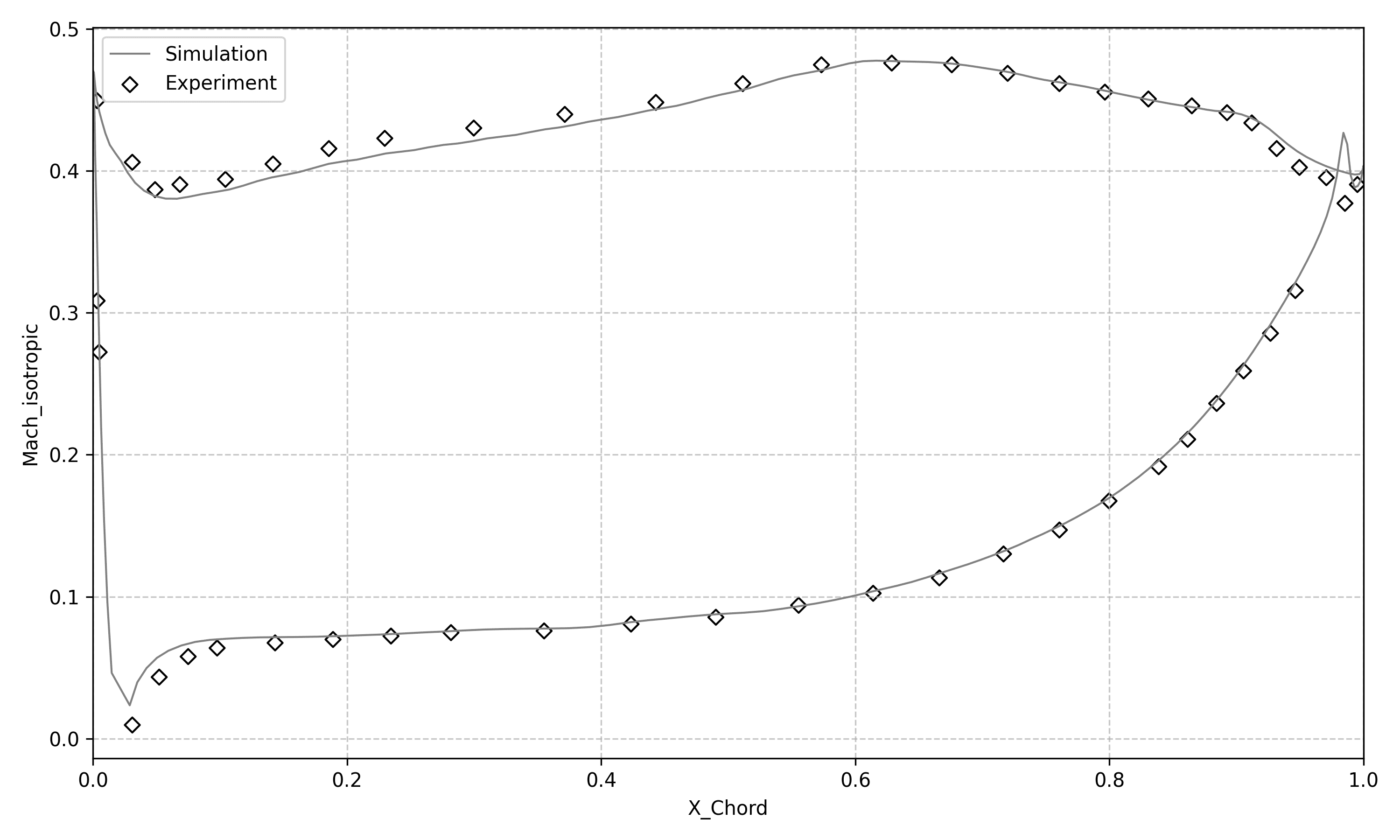
It is worth noting that in the analysis of numerous experimental and simulation data for T106A, various degrees of correction have been applied to the inlet metal angle. This is because in the T106A steady-state experiments, the upstream wake generator was not removed. This effect is not present in T106C.
Results:
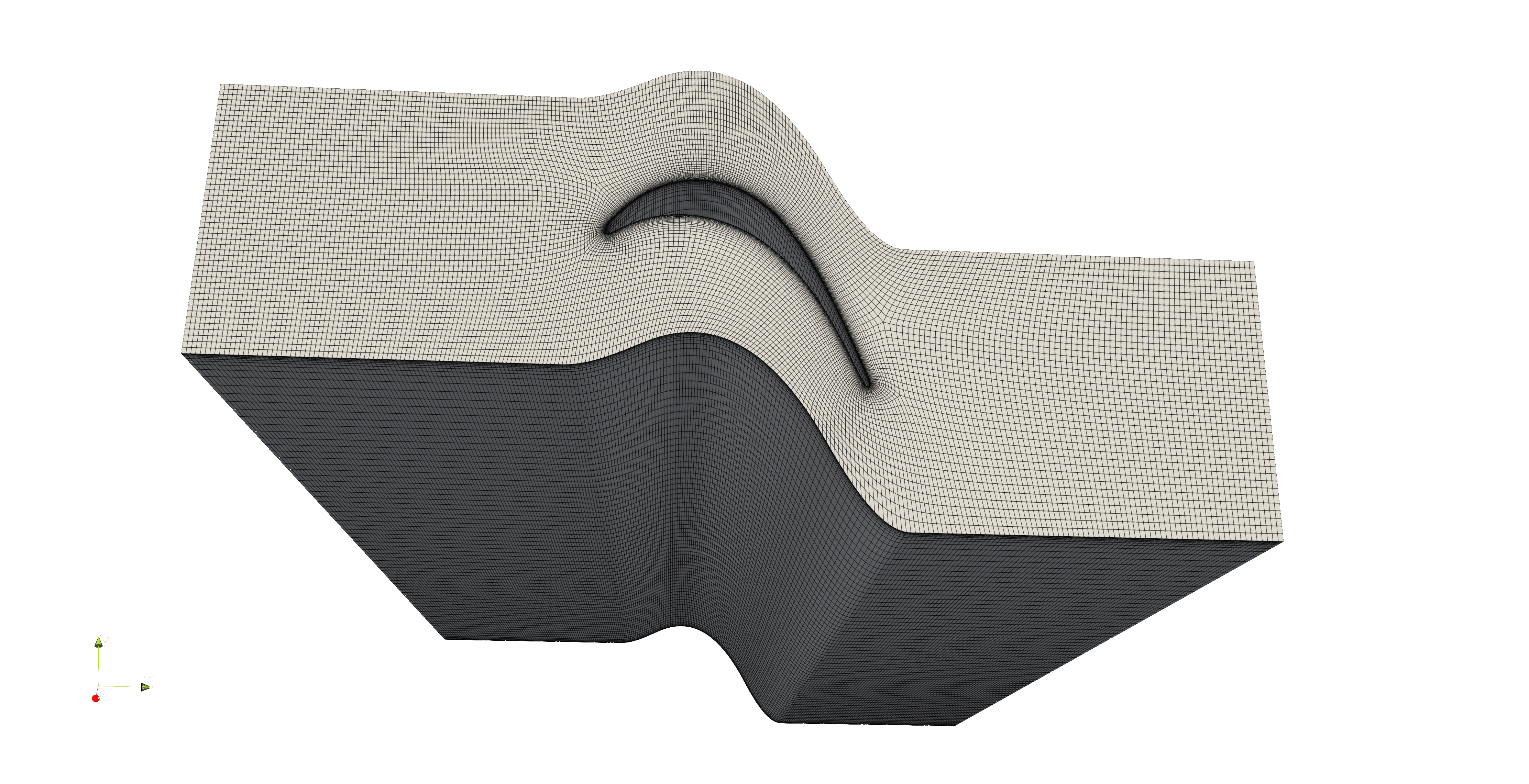
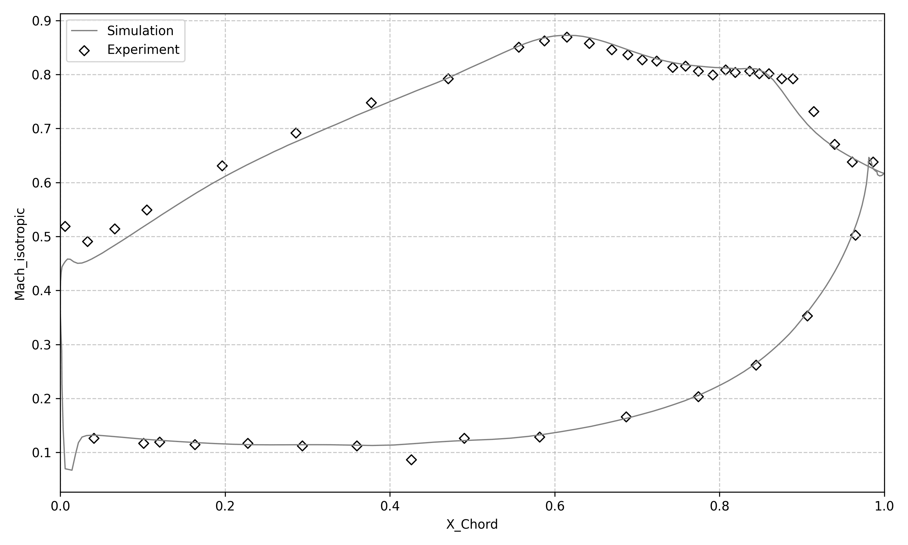
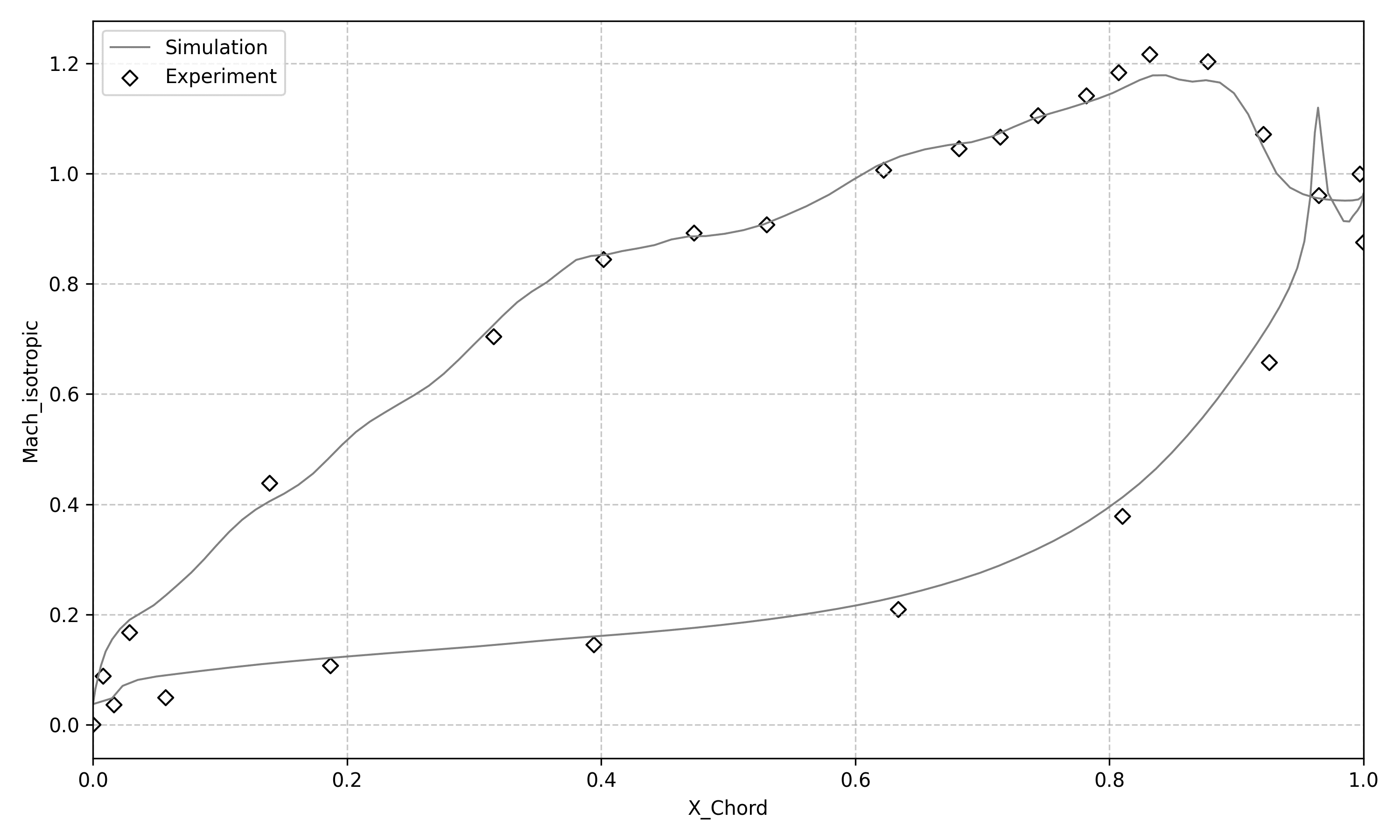
T106C
Data Source: Jan Michálek, Michelangelo Monaldi, Tony Arts, AERODYNAMIC PERFORMANCE OF A VERY HIGH LIFT LOW PRESSURE TURBINE AIRFOIL (T106C) AT LOW REYNOLDS AND HIGH MACH NUMBER WITH EFFECT OF FREE STREAM TURBULENCE INTENSITY, ASME Turbo Expo 2010: Power for Land, Sea and Air, 10.1115/GT2010-22884
Mesh Information and Computational Configuration:
| Parameter | Value | Unit |
|---|---|---|
| Total Mesh Count | 1482740 | |
| ywall | 1e-6 | m |
| zwall | 1e-6 | m |
| Maximum Aspect Ratio | 800 | |
| Minimum Skew Angle | 45.8652 | |
| Inlet Total Temperature | 300 | K |
| Inlet Total Pressure | 10884.18658 | Pa |
| Outlet Static Pressure | 8193.935308 | Pa |
| Inlet Metal Angle | 32.7 | ° |
| Inlet Turbulence Intensity | 0.9 | % |
Results:
VKI LS89
Case Introduction:
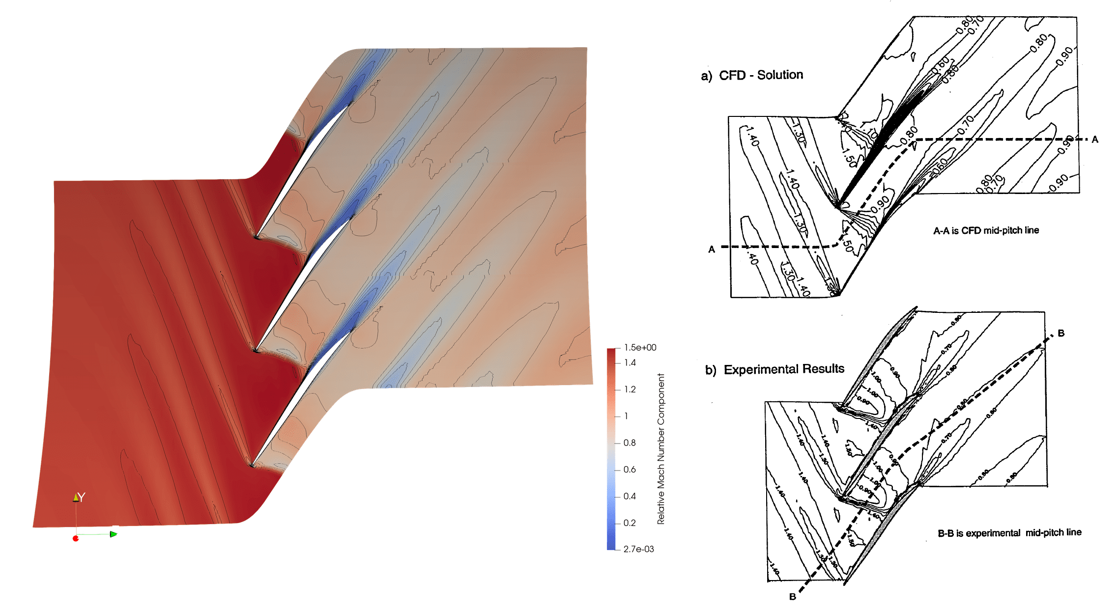
LS89 is a high-pressure turbine guide vane designed by the von Kármán Institute for Fluid Dynamics (VKI) in Belgium, renowned for its high-loading characteristics. The flow is typically high-speed, high Reynolds number, and accompanied by significant secondary flow losses, making it a classic case for studying secondary flows (such as horseshoe vortices and passage vortices) and total pressure loss generation mechanisms. These complex three-dimensional flow structures impose high requirements on mesh structure and local refinement strategies, especially for the endwall region meshes. Additionally, under certain operating conditions, LS89 may also exhibit local shock waves, further increasing the complexity of the flow field and mesh. VKI has conducted extensive experimental tests on LS89, providing high-quality performance and flow field measurement data, which serves as an important resource for CFD validation.
Data Source: T. Arts, M. Lambert de Rouvroit, A.W. Rutherford, AERO-THERMAL INVESTIGATION OF A HIGHLY LOADED TRANSONIC LINEAR TURBINE GUIDE VANE CASCADE, von KARMAN INSTITUTE FOR FLUID DYNAMICS, Technical Note 174
Mesh Information and Computational Configuration:
| Parameter | Value | Unit |
|---|---|---|
| Total Mesh Count | 634296 | |
| ywall | 5e-5 | m |
| zwall | 1e-6 | m |
| Maximum Aspect Ratio | 500 | |
| Minimum Skew Angle | 53.2659 | |
| Inlet Total Temperature | 420 | K |
| Inlet Total Pressure | 159600(MUR45)/147500(MUR47) | Pa |
| Outlet Static Pressure | 83300(MUR45)/87000(MUR47) | Pa |
| Inlet Metal Angle | 0 | ° |
| Inlet Turbulence Intensity | 1 | % |
Results:
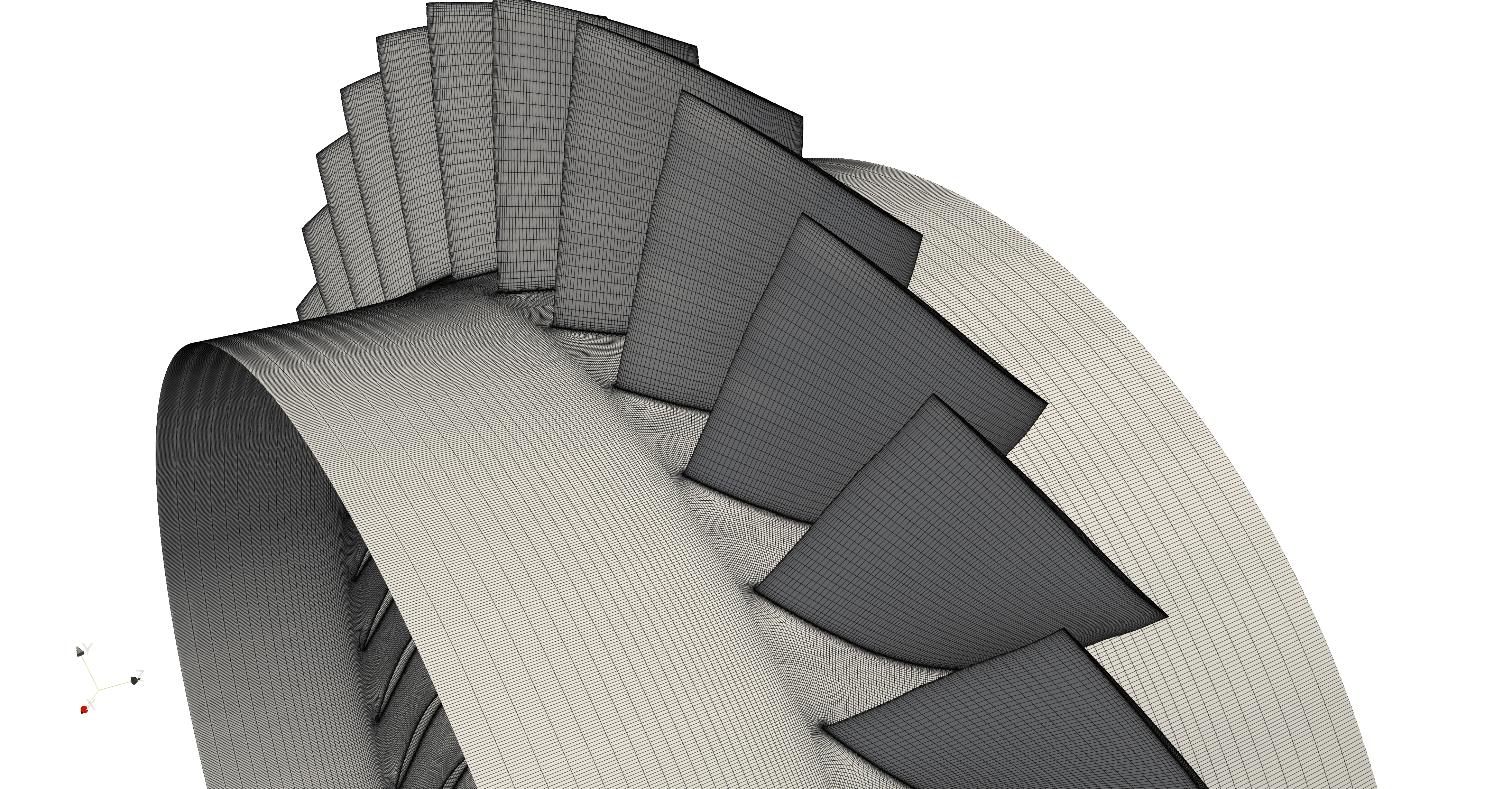
Rotor37
Case Introduction:
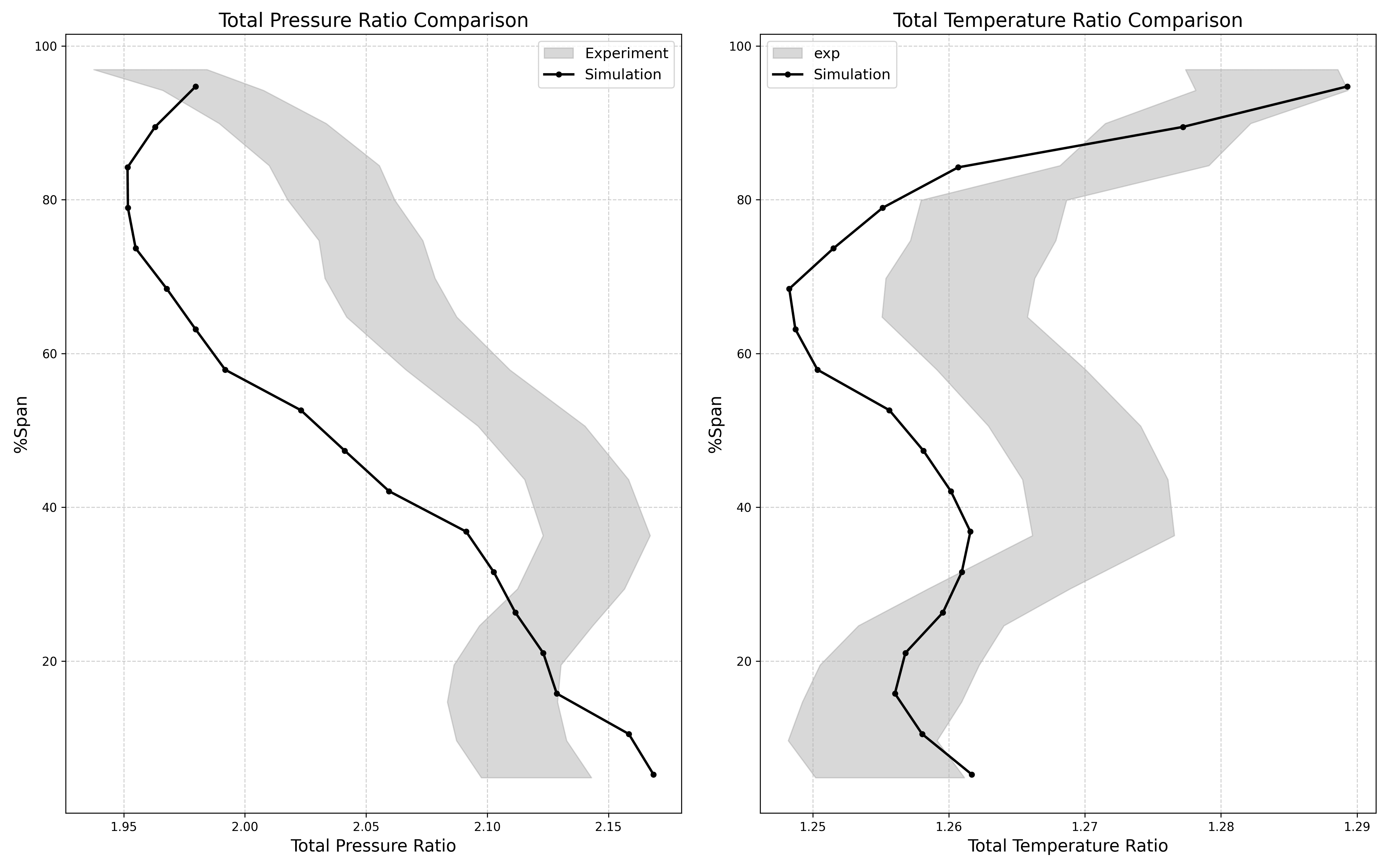
Rotor37 and Rotor67 are both classic transonic axial compressor rotors designed and tested by NASA, widely used for studying complex phenomena such as high Mach number flows, shock-boundary layer interactions, tip clearance flows, and near-stall operating conditions.
Rotor37 was designed and built by NASA Glenn Research Center, with design objectives of achieving high efficiency and high pressure ratio. It was specifically designed to study the behavior of transonic flow in compressor blades, aiming to provide a foundation for more efficient aero-engine compressor designs. Rotor37 exhibits transonic flow at its design point and throughout most of its operating range. As a single-stage rotor, Rotor37 is capable of producing a relatively high total pressure ratio, which is an important indicator for compressor performance.
Data Source: Lonnie Reid and Royce D. Moore, Design and Overall Performance of Four Highly Loaded, High-Speed Inlet Stages for an Advanced High-Pressure-Ratio Core Compressor, NASA Technical Paper 1337
Mesh Information and Computational Configuration:
| Parameter | Value | Unit |
|---|---|---|
| Total Mesh Count | 1831892 | |
| ywall | 1.0392e-6 | m |
| zwall | 7.2586e-7 | m |
| Maximum Aspect Ratio | 1227.47 | |
| Minimum Skew Angle | 5.7240 | |
| Inlet Total Temperature | 288.15 | K |
| Inlet Total Pressure | 101325 | Pa |
| Outlet Static Pressure | 118000 | Pa |
| Rotational Speed | (0,0,-1799.8519) | rad/s |
| Total Pressure Ratio | 2.026 | |
| Total Temperature Ratio | 1.260 | |
| Outlet Mass Flow Rate | 20.721 | kg/s |
| Efficiency | 85.97% |
Results:
Rotor67
Case Introduction:
Rotor67 is the first-stage rotor of a two-stage fan designed by NASA Lewis, with the core design objective of significantly improving overall fan performance and efficiency. Its most notable feature is the adoption of a low aspect ratio, aimed at eliminating the mid-span dampers traditionally required in turbomachinery fans to suppress blade vibration and improve aerodynamic stability, thereby simplifying the structure and reducing aerodynamic losses. Experimental results demonstrated that it achieved efficiency exceeding expectations at the design pressure ratio, with the first-stage rotor achieving an adiabatic efficiency of 0.906, which is 2 percentage points higher than the design target. Additionally, the optimized radial load distribution also enables the fan to better handle boundary layer defects in the tip region, further enhancing overall performance. Rotor67 consists of 22 multiple-circular-arc blades, designed for axial inlet flow without requiring inlet guide vanes. M. J. Pierzga et al. obtained laser velocimeter and aerodynamic performance data for this design under operating conditions near peak efficiency and near stall, which can be used for comparative analysis with simulation calculations.
Data Source: M. J. Pierzga, J.R. Wood, Investigation of the Three-Dimensional Flow Field Within a Transonic Fan Rotor: Experiment and Analysis, NASA Technical Memorandum 83739
Mesh Information and Computational Configuration:
| Parameter | Value | Unit |
|---|---|---|
| Total Mesh Count | 2459466 | |
| ywall | 1.095E-6 | m |
| zwall | 6.38E-7 | m |
| Maximum Aspect Ratio | 1532.55 | |
| Minimum Skew Angle | 7.6314 | |
| Inlet Total Temperature | 300 | K |
| Inlet Total Pressure | 101325 | Pa |
| Outlet Static Pressure | 120000 | Pa |
| Rotational Speed | (0,0,-1679.98) | rad/s |
| Total Pressure Ratio | 1.561 | |
| Total Temperature Ratio | 1.152 | |
| Outlet Mass Flow Rate | 34.446566 | kg/s |
| Efficiency | 89.10% |
Results:

NACA0015
Case Introduction:
NACA0015 is a perfectly symmetric airfoil with a maximum thickness of 15% of the chord length. Although it is a very basic airfoil, in certain applications, particularly where lift generation in both forward and reverse directions is required, such as helicopter rotor pitch-varying blades, symmetric airfoils may be an appropriate choice. Additionally, due to the need to maintain control capability at high angles of attack and typically not requiring lift generation at zero angle of attack, NACA0015 or its variants are commonly used for aircraft vertical tails and horizontal tails (straight wing profiles).
Results:
Mesh Information:
| Parameter | Value | Unit |
|---|---|---|
| Total Mesh Count | 137160 | |
| ywall | 5.377e-5 | m |
| zwall | 4.999e-2 | m |
| Maximum Aspect Ratio | 3715.02301450229 |
N4412
Case Introduction:
N4412 is also a very common NACA four-digit series airfoil with camber, which means it can generate lift at zero angle of attack. It is one of the preferred airfoils for many small general aviation aircraft wings because it provides sufficient lift at low speeds while also considering structural and manufacturing simplicity. When designing low to medium speed unmanned aerial vehicles, N4412 or its variants are often considered to achieve favorable lift-to-drag ratios.
Results:
Mesh Information:
| Parameter | Value | Unit |
|---|---|---|
| Total Mesh Count | 211608 | |
| ywall | 1.0e-5 | m |
| zwall | 4.999e-3 | m |
| Maximum Aspect Ratio | 3598.23560215619 |