Aerospace External Flow Cases
Official preprint:10.5281/zenodo.18933291
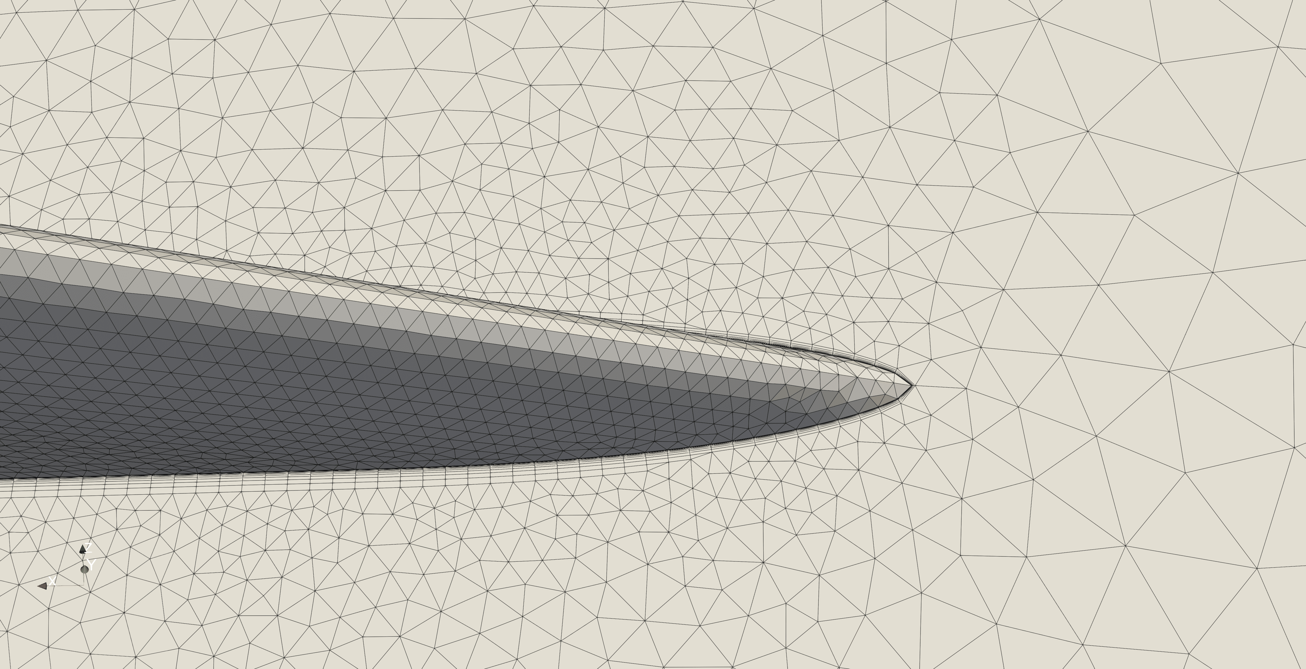
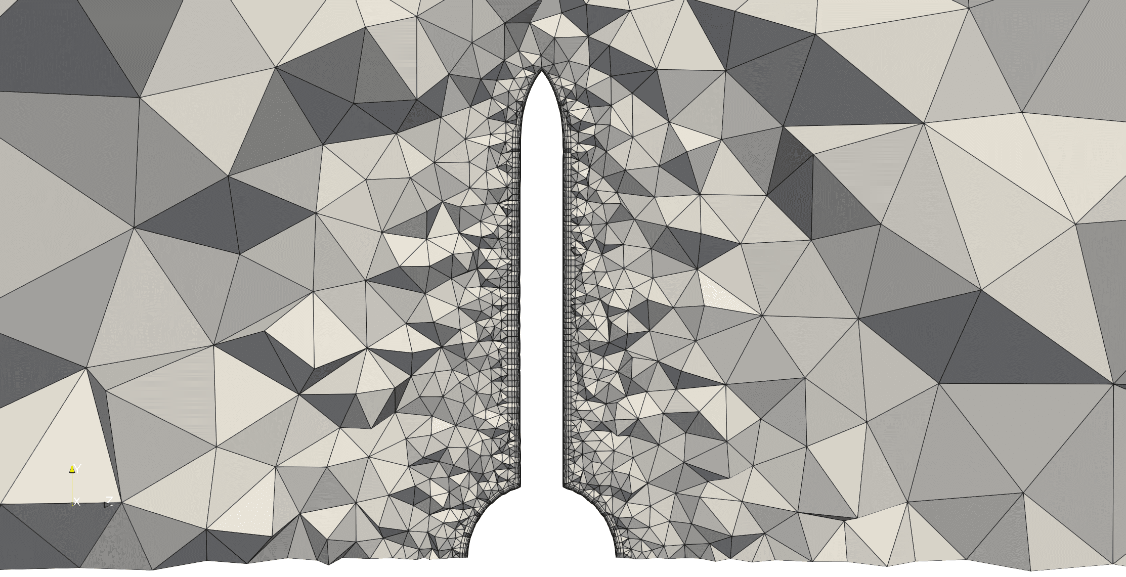
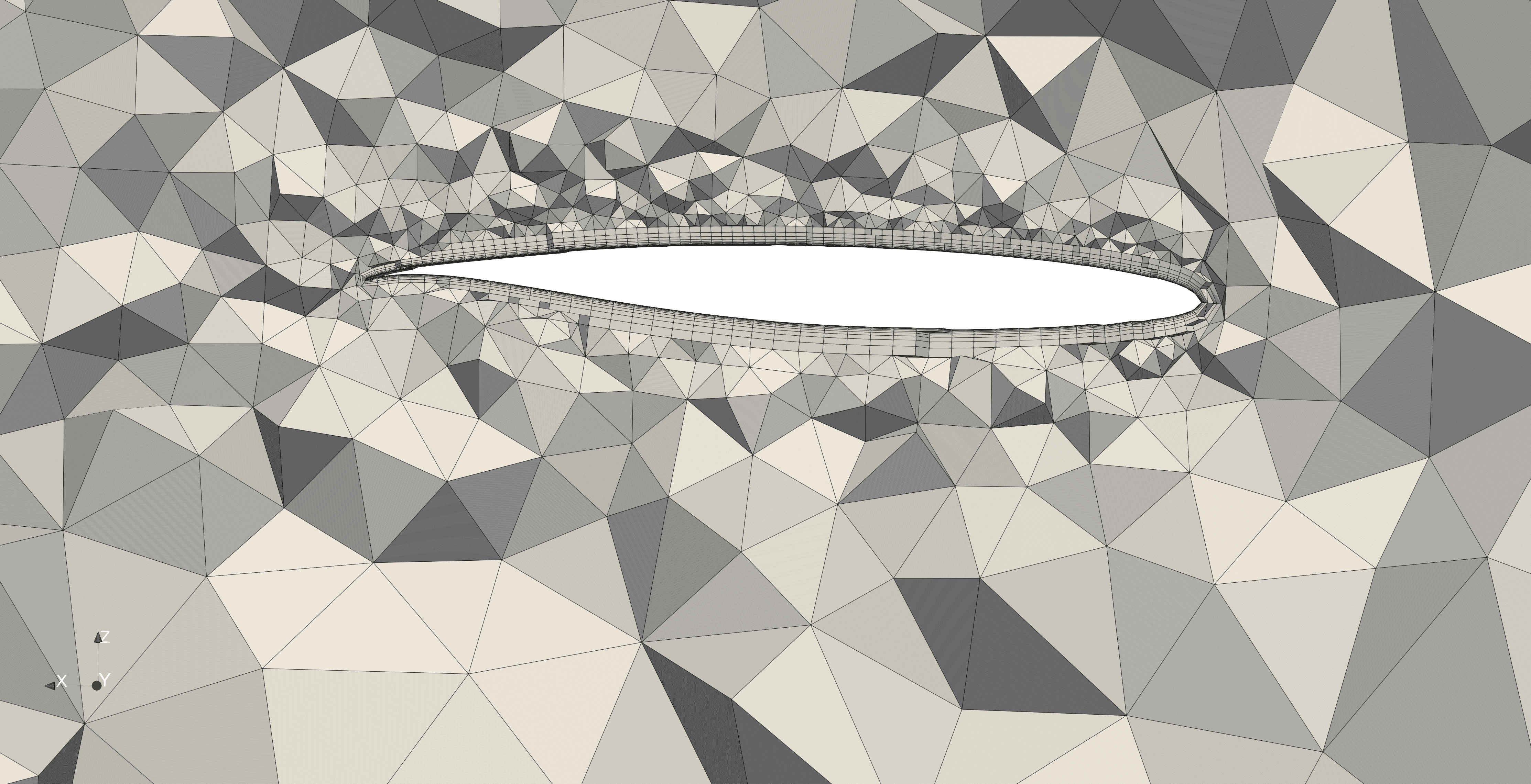
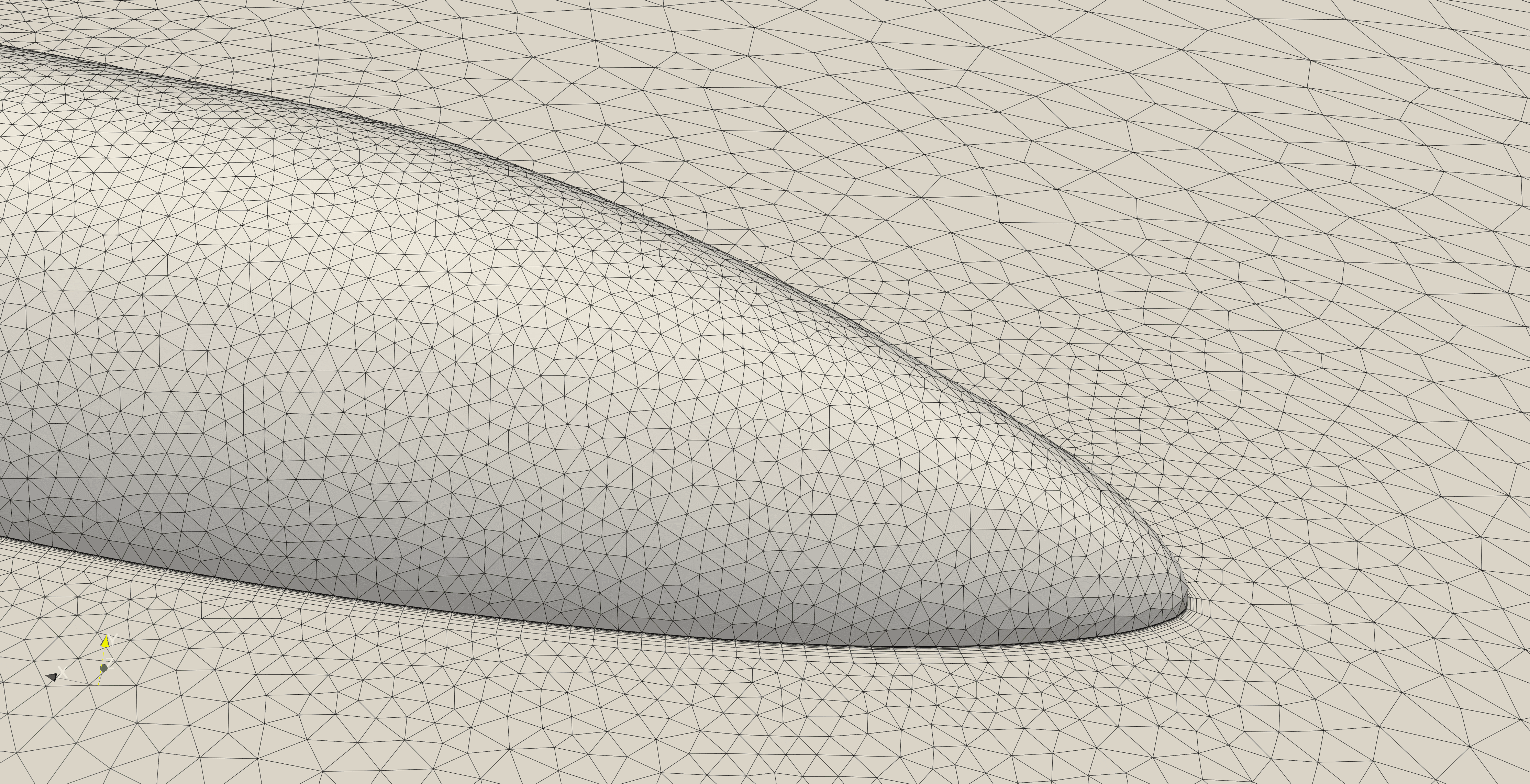
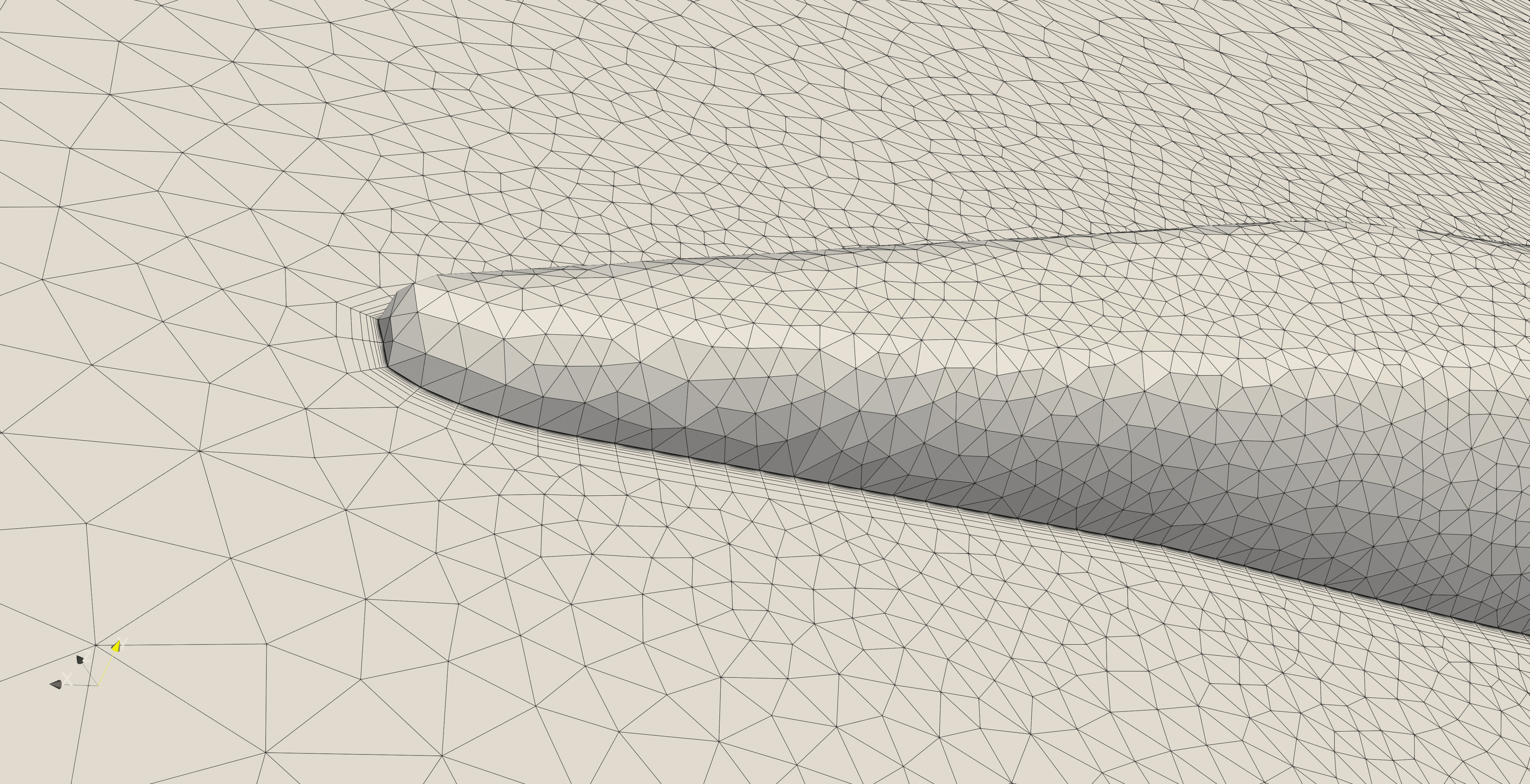
In the simulation of high-lift devices, accurately capturing their complex flow field characteristics is crucial, and this is precisely where the core value of boundary layer mesh generation and adaptive mesh refinement technology lies. Since fluid forms thin yet critical boundary layers near device walls, where velocity and physical quantities change dramatically, traditional uniform meshes cannot effectively resolve these regions. Therefore, we must apply refined semi-structured boundary layer meshes to capture key phenomena such as viscous effects, flow separation, and shock waves. This requirement for high aspect-ratio mesh elements is particularly urgent under high Reynolds number or high Mach number conditions, as they can efficiently resolve anisotropic flows. By combining automatic boundary layer mesh generation with adaptive mesh refinement based on CFD results, we can precisely focus computational resources on high-gradient regions in the flow field, significantly improving computational accuracy while substantially optimizing mesh count, thereby enhancing computational efficiency. This "a posteriori" error control approach not only enhances the reliability of simulation results but also simplifies mesh processing workflows for complex geometries and flow conditions.
In the following sections, we will demonstrate through a series of classic and representative cases, including the ONERA M6 wing (validating transonic shock wave and boundary layer interactions), the CRM wing-body configuration (showcasing complex wing-body interference and high Reynolds number cruise simulation), the 65° Delta Wing (capturing strong vortex structures and their coupling with boundary layers), and the DLR F11 high-lift configuration (simulating multi-element airfoil separation and attachment phenomena), comprehensively demonstrating the powerful versatility, accuracy, and efficiency of boundary layer mesh generation and adaptive mesh computation tools in addressing various aerodynamic challenges.
ONERA M6
Case Introduction:
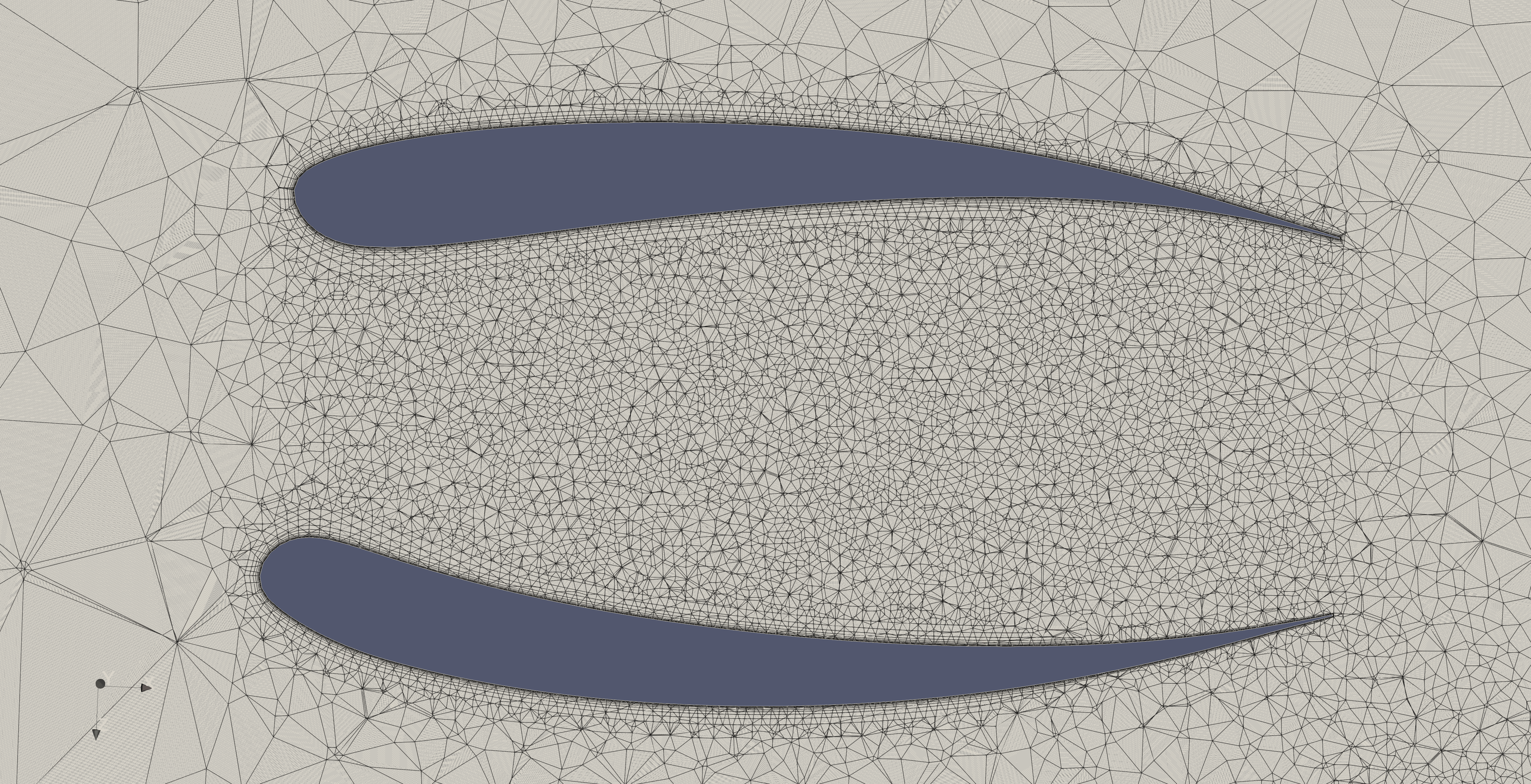
The ONERA M6 wing was designed by the French National Aerospace Research Center (ONERA) in the 1970s, with the primary objective of providing a standardized verification and evaluation platform for computational fluid dynamics (CFD) codes dealing with three-dimensional, high Reynolds number transonic flows. Although the ONERA M6 wing has a relatively simple geometric structure—a swept semi-span wing without twist, using the ONERA D symmetric airfoil section—it can produce complex phenomena under transonic conditions, including local supersonic flow, shock wave formation, and shock wave-boundary layer interactions (shock-induced separation), which impose extremely high requirements on numerical simulation accuracy. These characteristics make it a typical case for evaluating the capability of different numerical methods to capture transonic flow features (such as pressure distribution and shock position). The ONERA M6 wing has comprehensive wind tunnel experimental data, including surface pressure coefficient distributions at various Mach numbers and angles of attack, as well as aerodynamic performance parameters such as lift and drag coefficients, typically conducted at high Reynolds numbers to simulate actual flight conditions.
The simulation challenges of the ONERA M6 wing include accurately capturing the position, intensity, and structure of shock waves, which requires high-resolution meshes and appropriate numerical schemes; handling highly nonlinear and complex shock-boundary layer interaction viscous effects, which relies on refined near-wall meshes and accurate turbulence models; and the substantial computational cost associated with the fine meshes and advanced numerical methods required to accurately capture these complex phenomena—all of which make the ONERA M6 an ideal case for validating adaptive mesh refinement and efficient algorithms.
Data Source: Schmitt, V. and F. Charpin, "Pressure Distributions on the ONERA-M6-Wing at Transonic Mach Numbers," Experimental Data Base for Computer Program Assessment. Report of the Fluid Dynamics Panel Working Group 04, AGARD AR 138, May 1979.
Mesh Generation Configuration: The M6_ADAPT.json used for the first computation is shown below. We first use the pressure field to capture shock waves on the wing surface, then use the Mach number field to adaptively refine the remaining volume mesh.
{
    "Function": {
        "Volume_genration_from_cad":false,// Whether to generate volume mesh from CAD
        "Layer_gneration":false,// Whether to generate boundary layer mesh, set to true in the second stage
        "Open_layer":true,// Use open method for boundary layer mesh generation
        "Mesh_adaptation":true,// Whether to enable mesh adaptation
        "Mesh_adaptation_with_layer":false,// Whether to apply adaptation to boundary layer mesh
        "Mesh_optimize_sdf":false
    },
    "Inputfile":{
        "Geofile":"",// Input CAD filename
        "Meshfile":"mesh_M6-org.su2",// Input mesh filename
        "SU2script":"M6-EULER.cfg"// Simulation configuration filename, use "M6-RANS.cfg" in the second stage
    },
    "Inputparameter":{
        "Target_surface_tag_org":[1],// Surface tags for boundary layer generation
        "Scale":1,// Mesh scaling factor
        "Domain_type":"box",// Mesh generation domain type
        "Domain_length":11,// Characteristic length of mesh generation domain
    },
    "Meshing":{
        "Ywall":1e-6,// Boundary layer first cell height
        "Use_expension":true,// Use boundary expansion method
        "Use_least_square":true,// Use least squares method
        "Min_meshsize":0.001,// Minimum mesh size
        "Max_meshsize":2,// Maximum mesh size
    },
    "Mesh_Adaptation":{
        "Use_physical_parameter":"Pressure",// Physical field for adaptation, change to "Mach" in the second stage
        "Isotropic":true,// Whether to use isotropic adaptation
        "Smooth_iteration":20,// Number of smoothing iterations
        "Iteration":10,// Number of adaptation iterations
        "Use_restart":false,// Use hot restart for computation
        "Initial_cal_iteration":2000,// Initial computation iterations
        "Rest_cal_iteration":2000,// Restart computation iterations
        "Initial_cal_cfl":20,// Initial computation CFL number
        "Rest_cal_cfl":20,// Restart computation CFL number
    },
    "Outputfile":{
        "SU2mesh":"M6-layer.su2"// Output boundary layer mesh filename
    }
}
| Parameter | Value | Unit |
|---|---|---|
| AOA | 3.06 | ° |
| Freestream Mach Number | 0.84 | |
| Freestream Reynolds Number | 14.6E6 | |
| Freestream Temperature | 300 | K |
| CFL | 20 | |
| SU2 Solver | RANS+SA | |
| Numerical Scheme | JST+SCALAR_UPWIND |
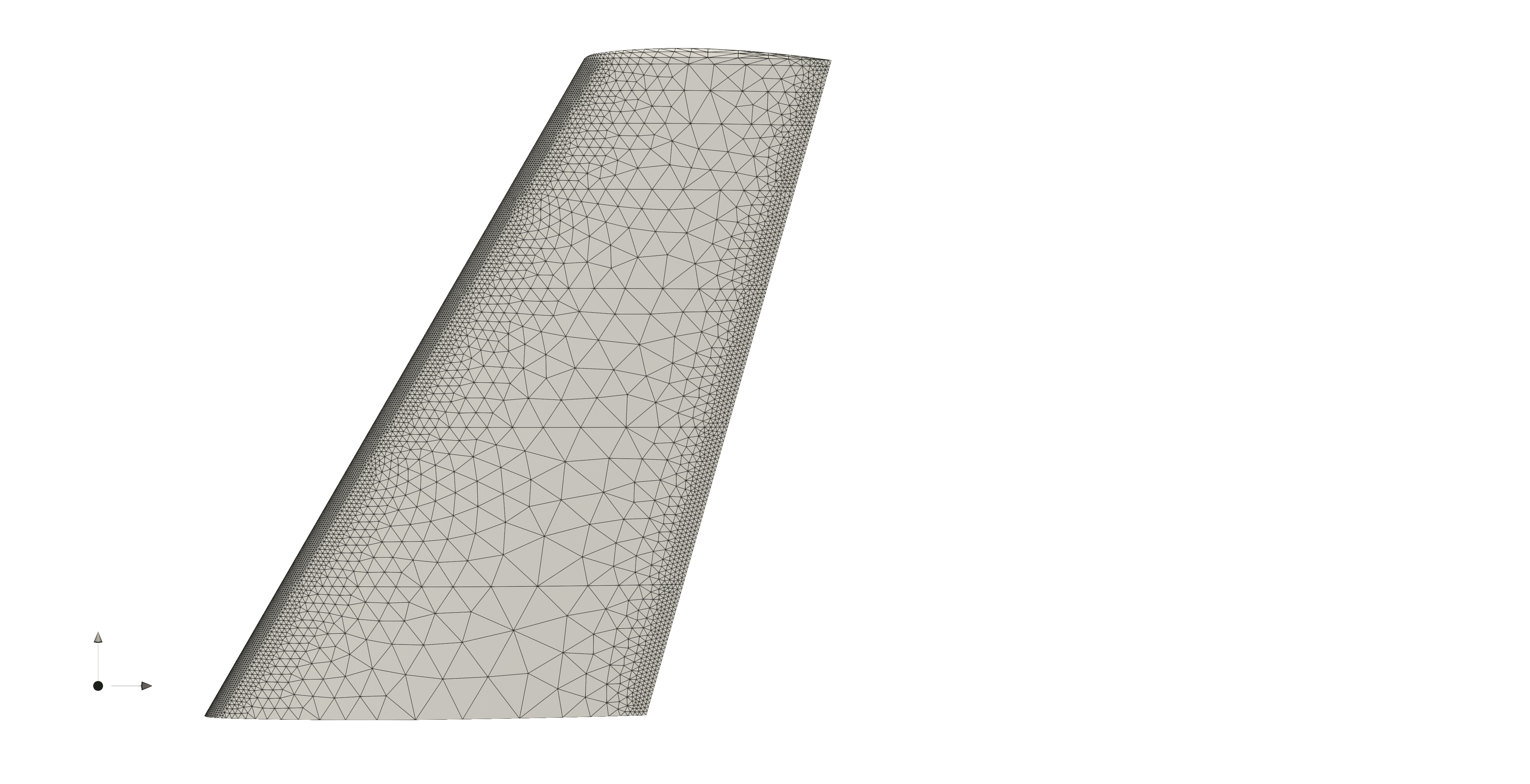
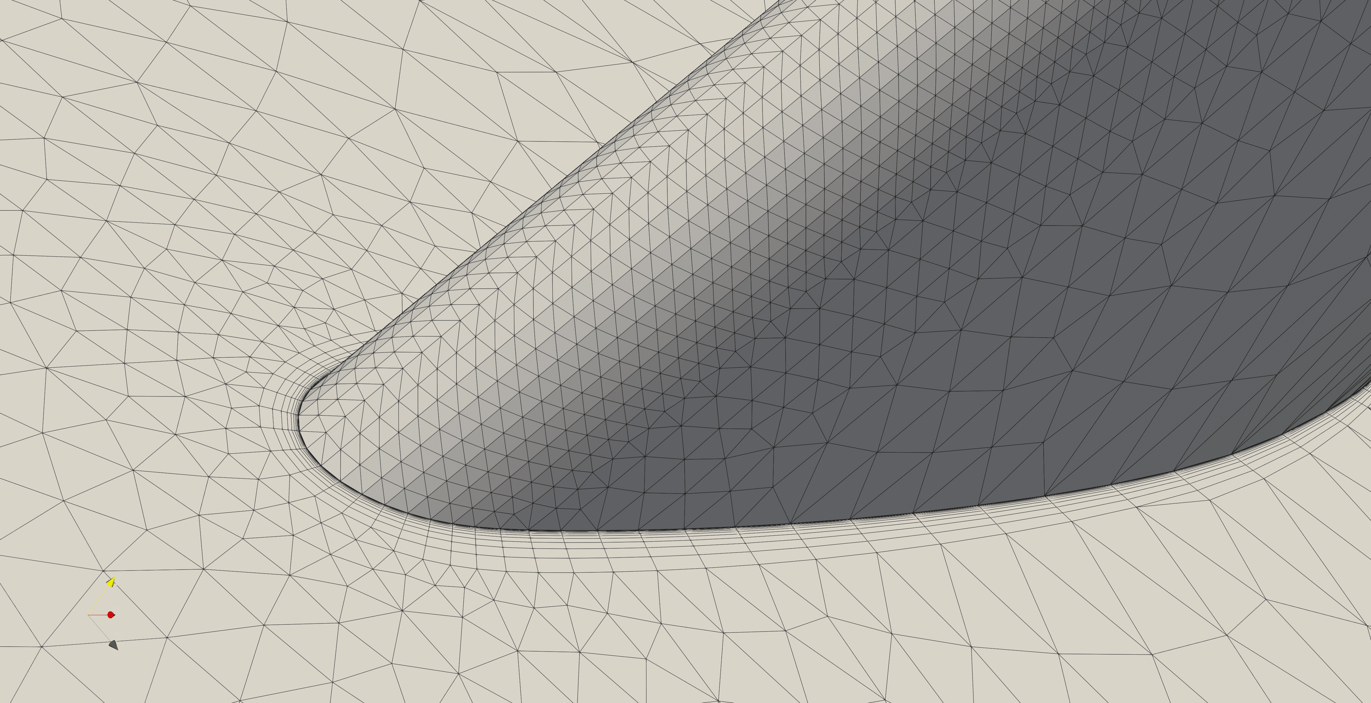
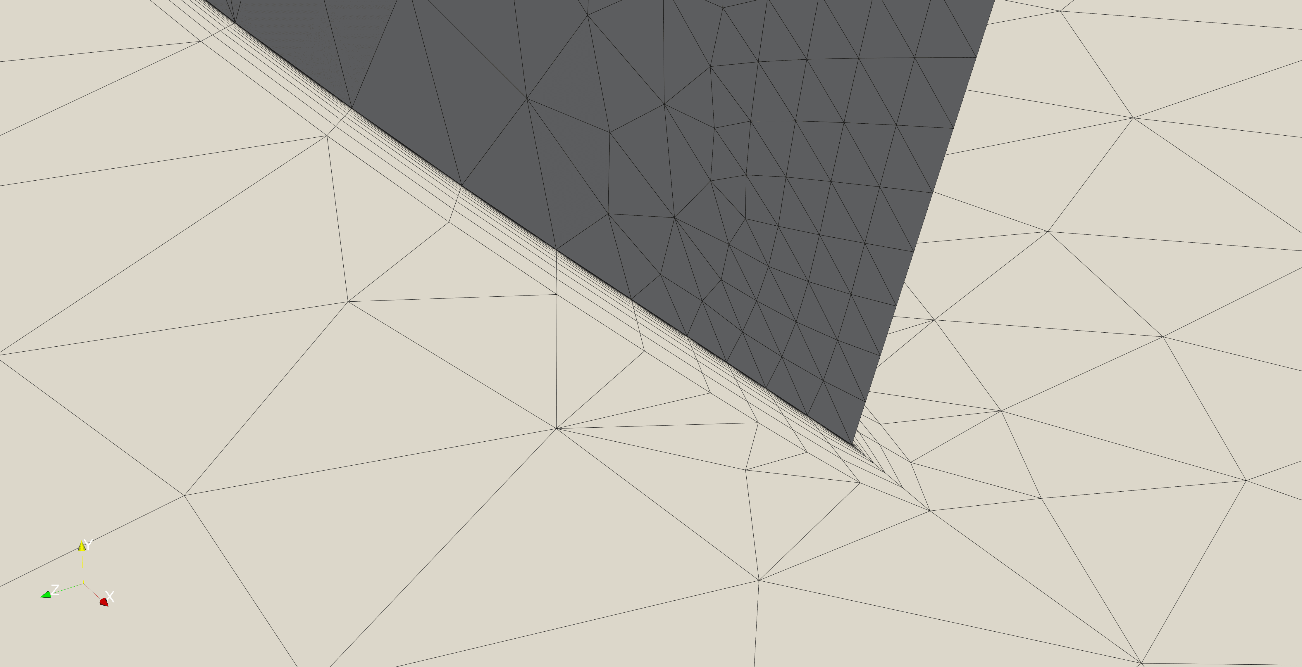
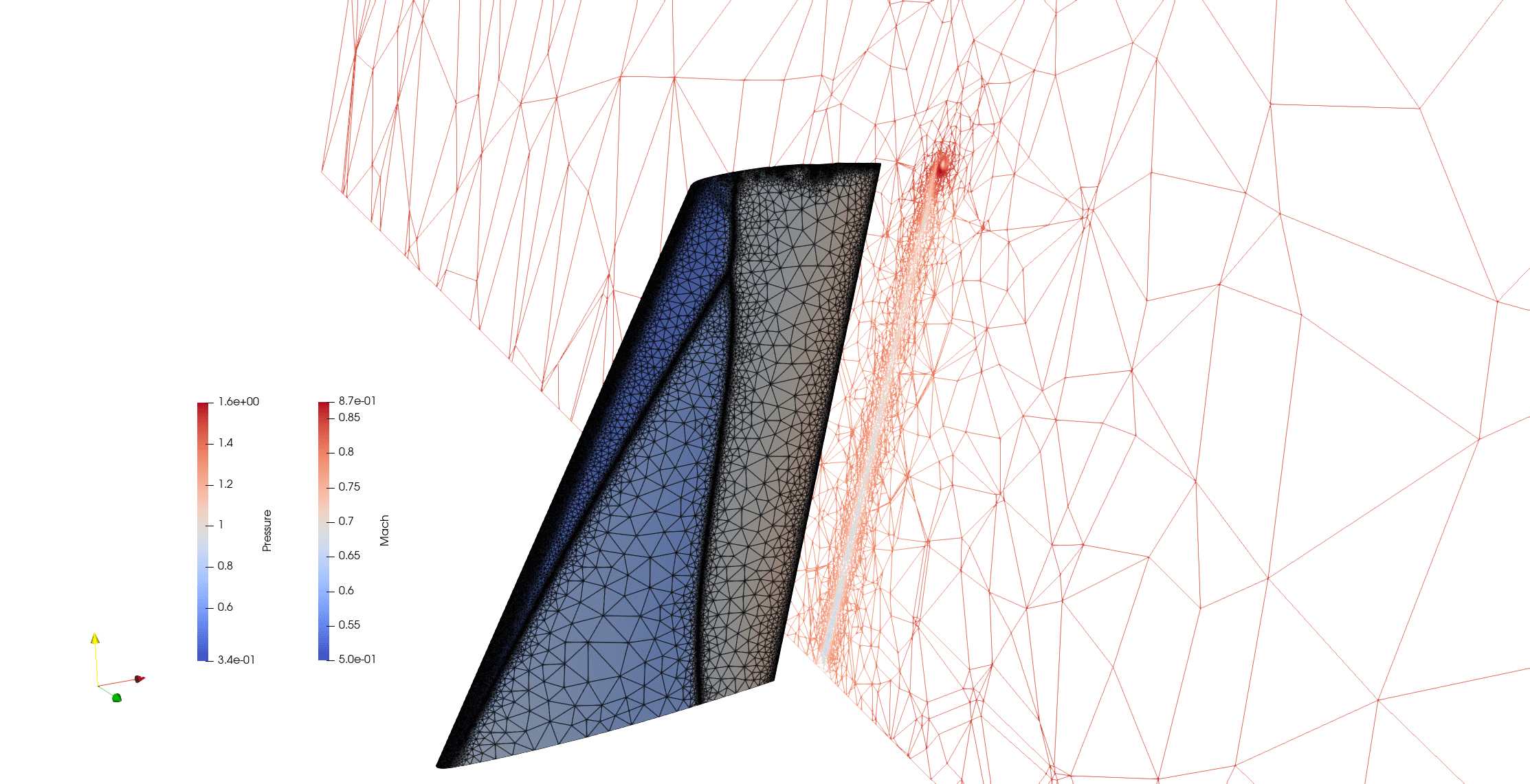
Results:
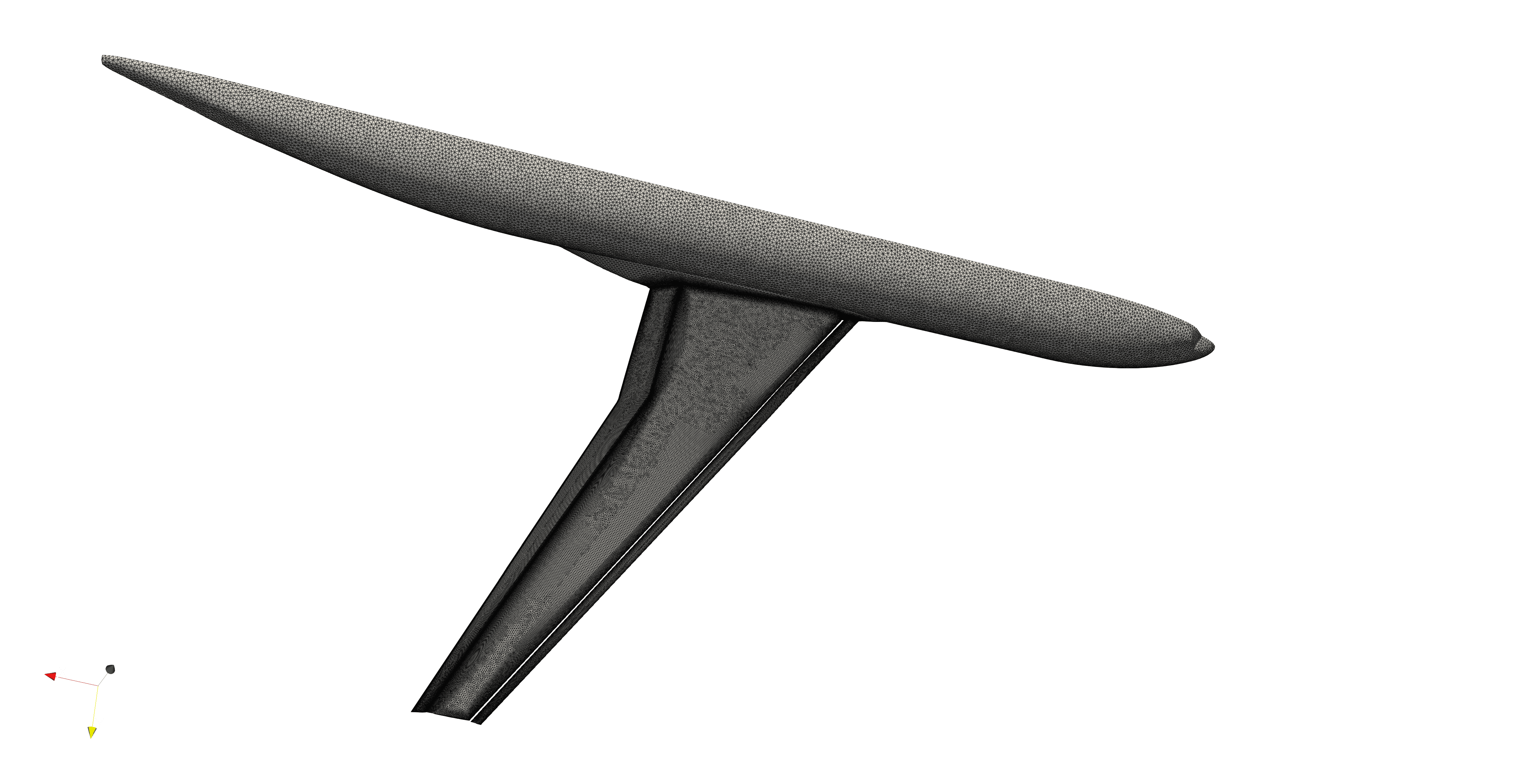
CRM
Case Introduction:
CRM, the Common Research Model, is a modern transonic wide-body aircraft model designed under the leadership of the National Aeronautics and Space Administration (NASA). Its design objective is to provide an open, standardized platform for Computational Fluid Dynamics (CFD) validation and research for the aviation industry and academic community. CRM aims to address the discrepancies in CFD results caused by the lack of a unified benchmark model, thereby promoting improvements in the accuracy, reliability, and efficiency of CFD codes.
The distinctive feature of CRM lies in its geometric configuration, which represents a modern supercritical transonic wing and typical wide-body aircraft fuselage. This enables it to simulate realistic flight conditions and generate complex flow phenomena such as shock waves, shock-boundary layer interactions, and wake flows. Its geometric information is publicly available and exists in multiple versions, such as the CRM for high-speed cruise conditions (M=0.85) and the High Lift CRM version for high-lift low-speed conditions, providing convenience for CFD research across different flight phases. Regarding experimental information, the CRM model has undergone extensive testing in multiple NASA wind tunnels, such as the National Transonic Facility (NTF) and the 14x22-foot Subsonic Wind Tunnel at NASA Langley Research Center. These experiments have produced extensive surface pressure distribution data, aerodynamic force/moment data, and other flow field measurements, which have become the gold standard for CFD simulation validation. These experimental data and their uncertainty quantification have been widely published in various open workshops (such as the AIAA Aerodynamic Design Optimization Discussion Group, ADODG) and literature, greatly advancing the development of CFD methods.
Compared to simple airfoils, CRM includes wings, fuselage, horizontal tail, engine nacelles, and pylons (some versions may not include vertical tail or engines), making mesh generation more complex and time-consuming, especially requiring refined meshes at component junctions and high-curvature regions. Furthermore, capturing complex flow mechanisms is challenging. CRM generates strong shock waves and shock-boundary layer interactions under transonic cruise conditions, while high-lift conditions involve large-scale flow separation, gap flows, and multi-body interference. All of these require high-precision numerical schemes, appropriate turbulence models, and sufficient mesh resolution for accurate simulation. The selection and validation of turbulence models are crucial for CRM simulations, as different RANS models may exhibit significant differences in predicting shock waves, separation, and wakes.
Data Source: https://commonresearchmodel.larc.nasa.gov/
Mesh Information and Computational Configuration(case3):
| Parameter | Value | Unit |
|---|---|---|
| AOA | 11.0 | ° |
| Freestream Mach Number | 0.2 | |
| Freestream Reynolds Number | 11.72E6 | |
| Freestream Temperature | 289.44 | K |
| CFL | 20 | |
| SU2 Solver | RANS+SA | |
| Numerical Scheme | JST+SCALAR_UPWIND |
Results:
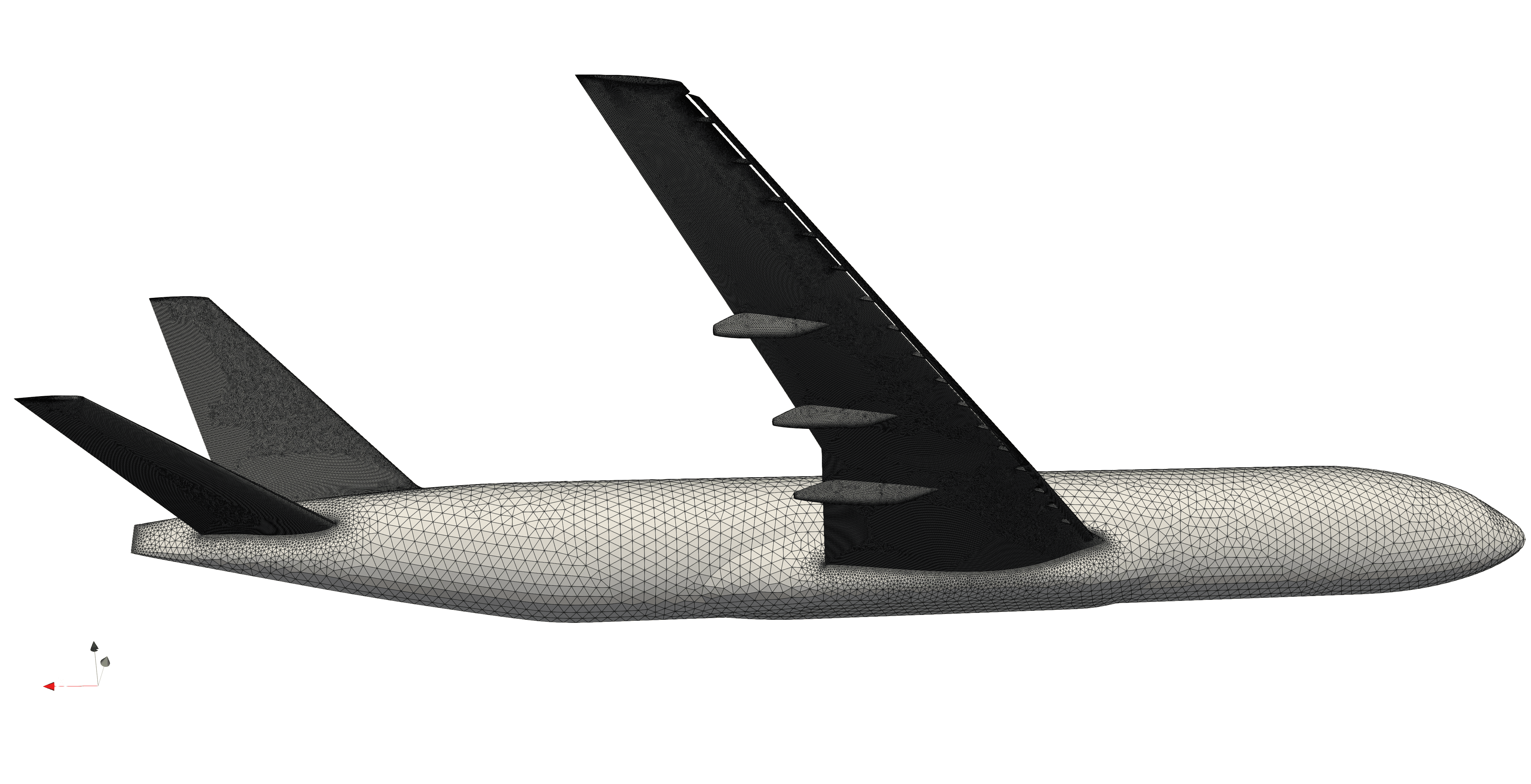
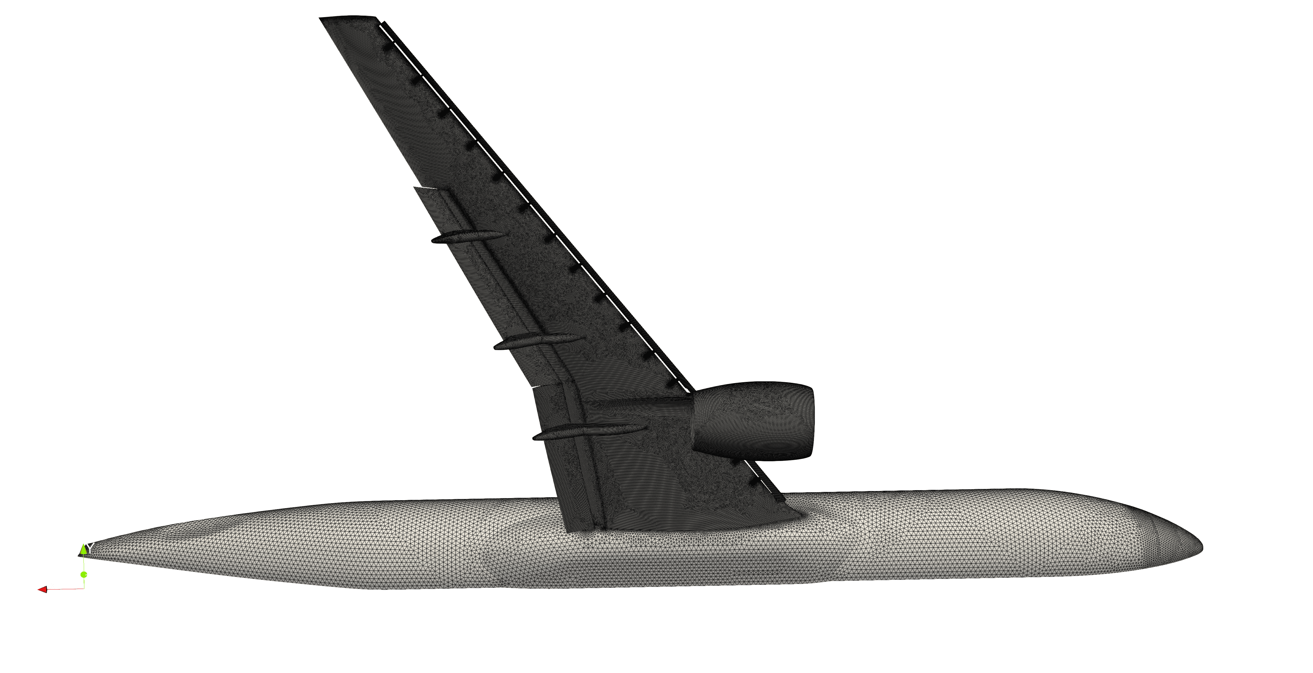

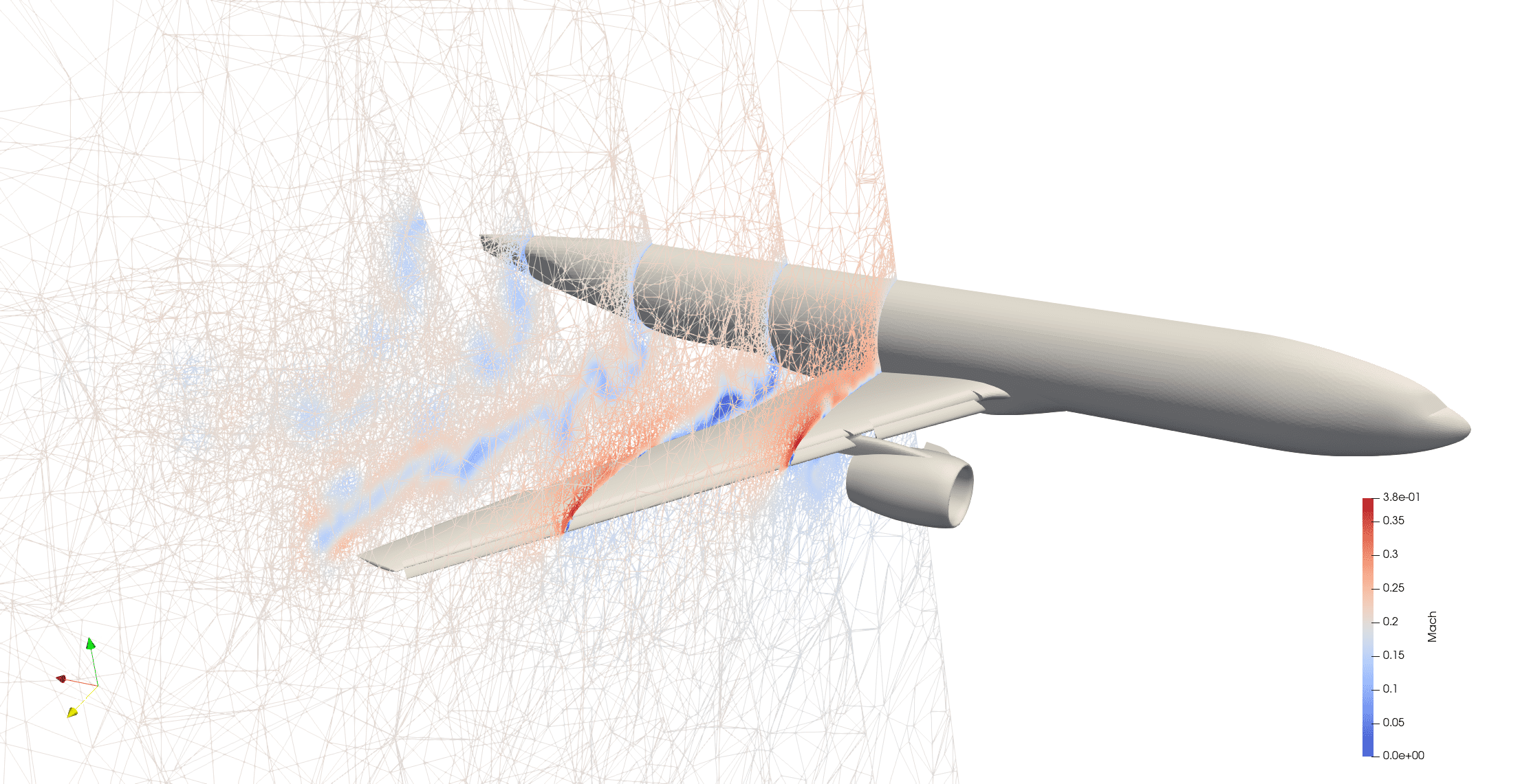
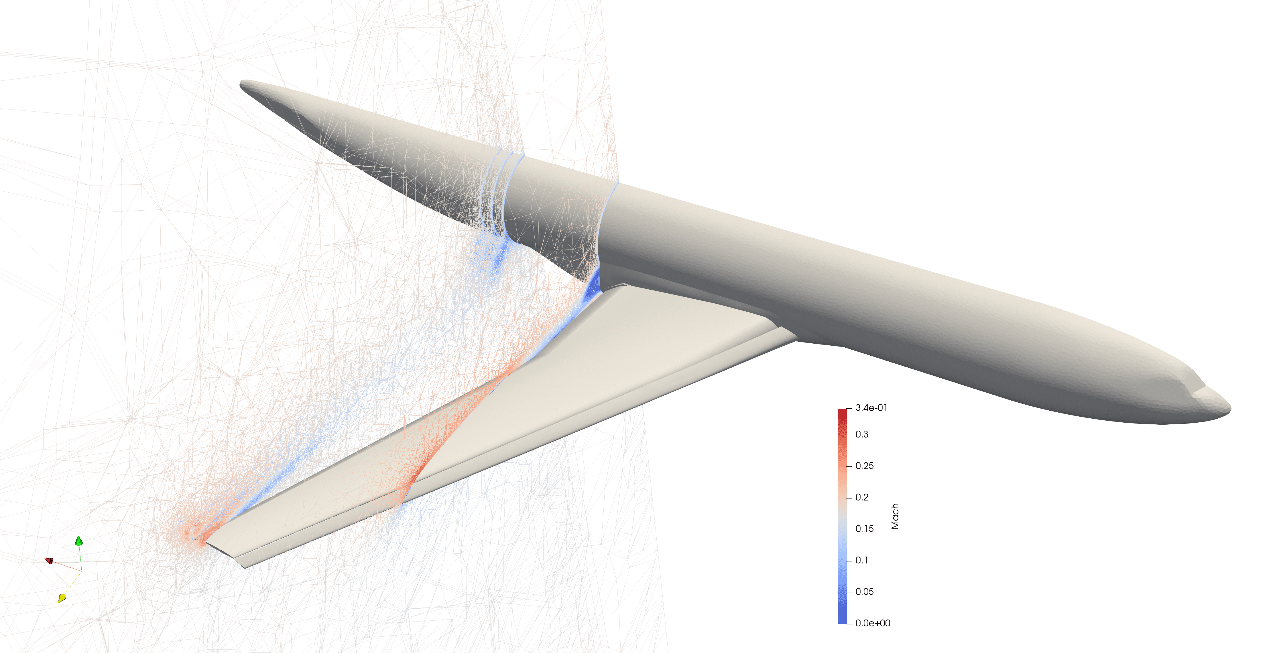
DLR F11
Case Introduction:
The DLR F11 model, designed by the German Aerospace Center (DLR), is a typical twin-engine regional aircraft configuration model. It aims to provide an open validation and research platform with detailed experimental data for aeroelastic design, aeroacoustic analysis, and more complex unsteady aerodynamic characteristics of civil aircraft, with particular focus on aeroelastic coupling phenomena under transonic cruise conditions. This model adopts a wing-body-horizontal tail configuration with twin-engine nacelles and pylons, simulating the geometric features of actual regional aircraft. It is the first to incorporate aeroelastic effects into design considerations, enabling deformation measurements coupled with aerodynamic forces. The DLR F11 has undergone extensive testing in advanced wind tunnels such as the European Transonic Windtunnel (ETW) at the German Aerospace Center. These experiments were conducted under high-pressure and cryogenic conditions approaching realistic flight Reynolds numbers, providing detailed data including surface pressure distributions, aerodynamic forces/moments, model deformations, and wall interference effects. These high-precision data are crucial for validating CFD capabilities in predicting complex flow fields, aerodynamic loads, and aeroelastic coupling.
Compared to the CRM (Common Research Model), which was primarily designed by NASA and focuses more on aerodynamic efficiency and flow mechanisms of modern wide-body aircraft under high-speed cruise conditions, the DLR F11 is more oriented toward the needs of the European aviation industry, representing a regional aircraft configuration. Its design and research direction place greater emphasis on aeroelastic coupling characteristics, aeroacoustics, and interactions with engine nacelles.
Data Source: R. Rudnik, K. Huber and S. Melber-Wilkending, EUROLIFT Test Case Description for the 2nd High Lift Prediction Workshop, 30th AIAA Applied Aerodynamics Conference, 25 - 28 June 2012, New Orleans, Louisiana
Results:
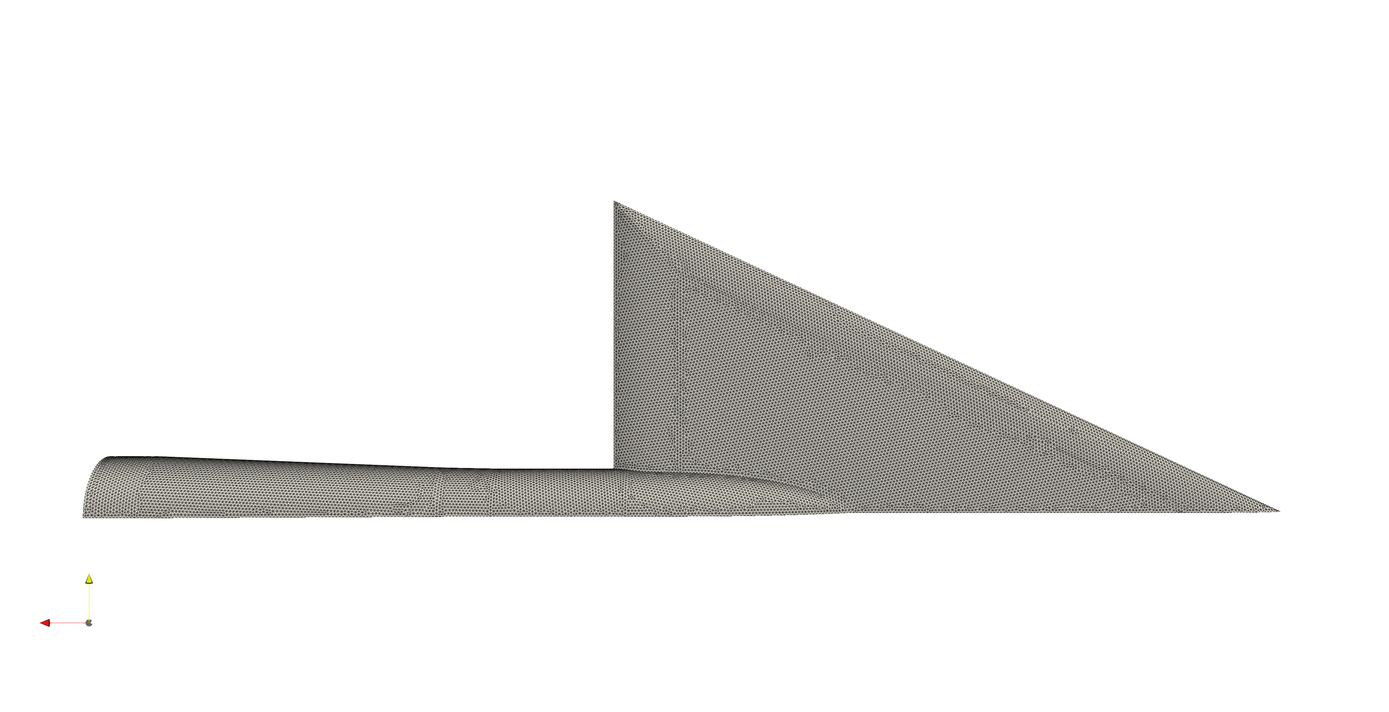
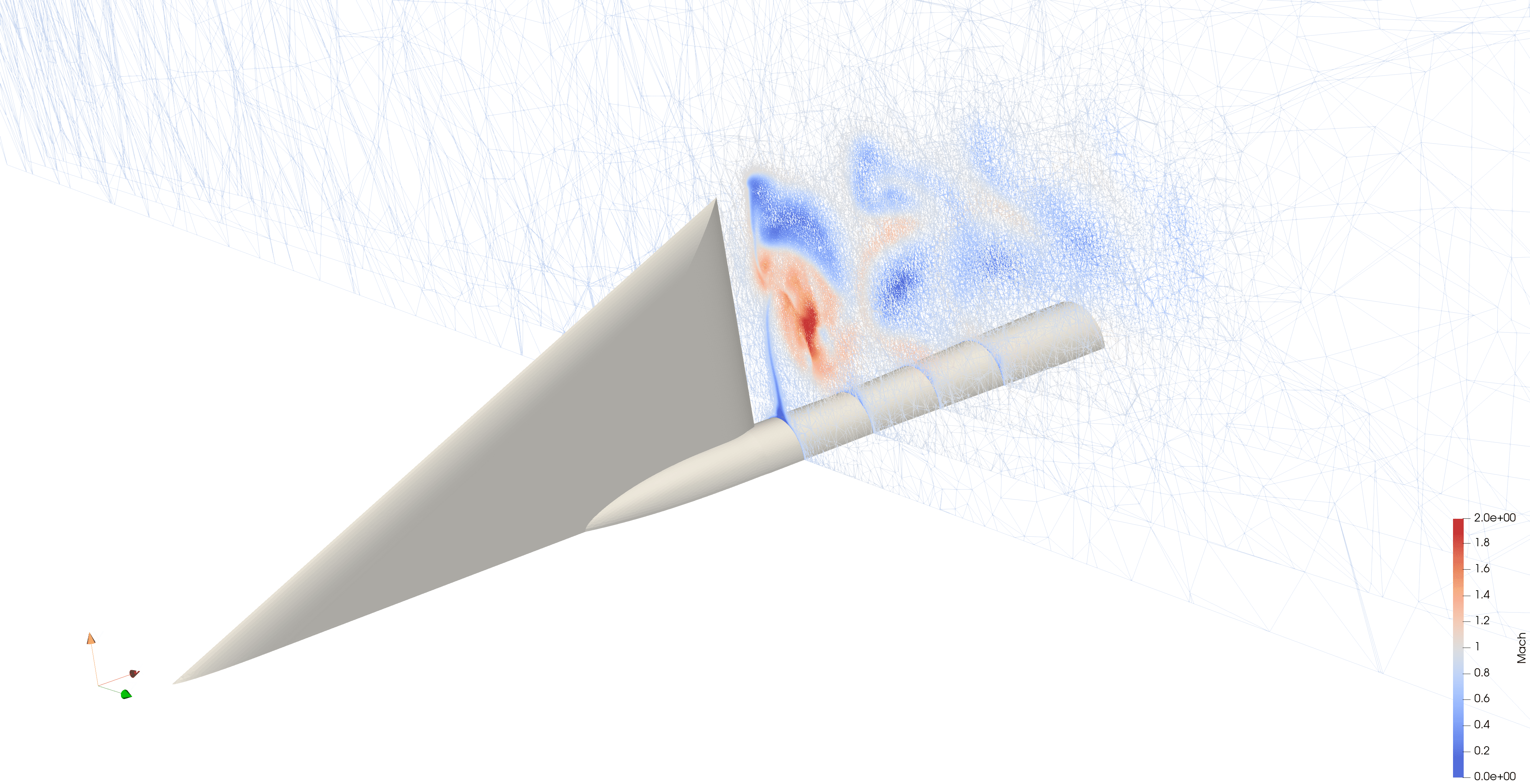
65° Delta Wing
Case Introduction:
The 65° Delta Wing is a generic benchmark model that has been extensively studied in the aviation field for investigating high angle-of-attack aerodynamic phenomena, vortex flow characteristics, and nonlinear aerodynamic forces of low aspect ratio delta wing configurations. Its concept and applications can be traced back to the early 20th century, particularly the pioneering research of German aviation pioneer Alexander Lippisch, which laid the foundation for subsequent delta wing designs. As a generic model, its design objective is to gain in-depth understanding of complex vortex aerodynamics, especially the mechanism by which Leading Edge Vortices (LEV) provide additional lift at high angles of attack, to provide reliable data for validating the accuracy of Computational Fluid Dynamics (CFD) methods, and to serve the design optimization of hypersonic vehicles and fighter aircraft. The model is characterized by its 65° high sweep angle, which effectively generates stable leading edge vortices, produces complex flow field characteristics, and features a relatively simple geometric structure, making it an ideal subject for studying nonlinear aerodynamic forces and vortex breakdown.
Major research institutions worldwide, such as NASA Langley Research Center, have conducted extensive experiments on this model across a wide range of Reynolds numbers and Mach numbers, providing abundant surface pressure, aerodynamic force/moment, and flow field visualization data. In particular, tests conducted at Reynolds numbers approaching realistic flight conditions in the NASA Langley National Transonic Facility (NTF) have provided important benchmarks for CFD model validation.
Despite its simple geometric structure, the simulation of the 65° Delta Wing still faces significant challenges, including accurate capture of highly nonlinear, three-dimensional complex vortex flows (especially vortex core breakdown phenomena), limitations in turbulence model selection, fine mesh generation to accommodate vortex motion and leading edge geometry, as well as numerical convergence and stability issues caused by strong nonlinearity at high angles of attack.
Data Source: Julio Chu and James M. Luckring, Experimental Surface Pressure Data Obtained on 65° Delta Wing Across Reynolds Number and Mach Number Ranges, Volume 1 - Sharp Leading Edge, NASA Technical Memorandum 4645, February 1996
Mesh Information and Computational Configuration:
| Parameter | Value | Unit |
|---|---|---|
| AOA | 26.7 | ° |
| Freestream Mach Number | 0.851 | |
| Freestream Reynolds Number | 6E6 | |
| Freestream Temperature | 322.59 | K |
| CFL | 20 | |
| SU2 Solver | RANS+SA | |
| Numerical Scheme | JST+SCALAR_UPWIND |
Results: