ACADEturbo User Manual
This manual guides you through the complete workflow from account registration to submitting a computation task.
1. Register an Account
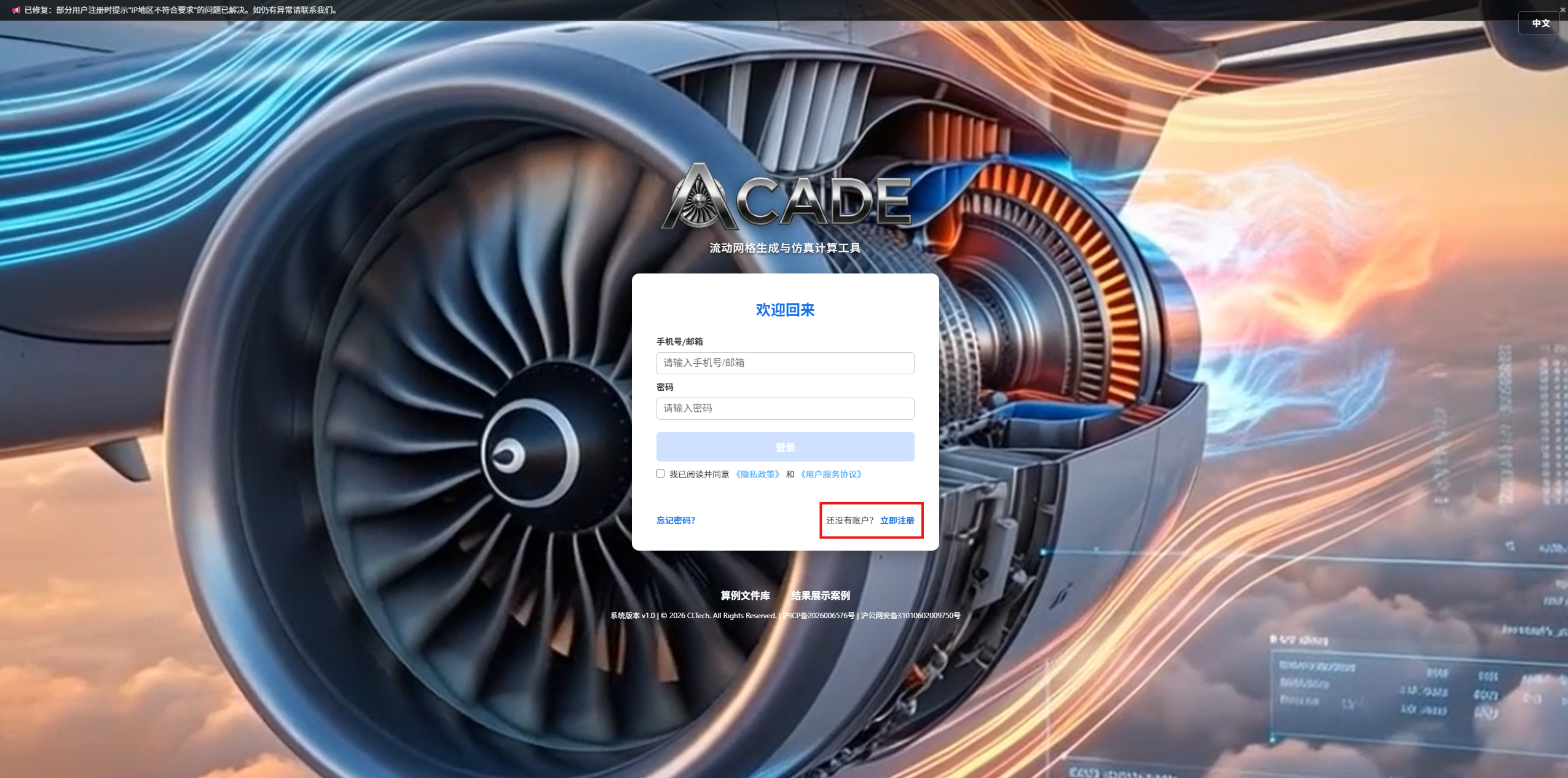
Visit https://www.acadeturbo.com/accounts/login/ and click the "Register now" link at the bottom of the page.
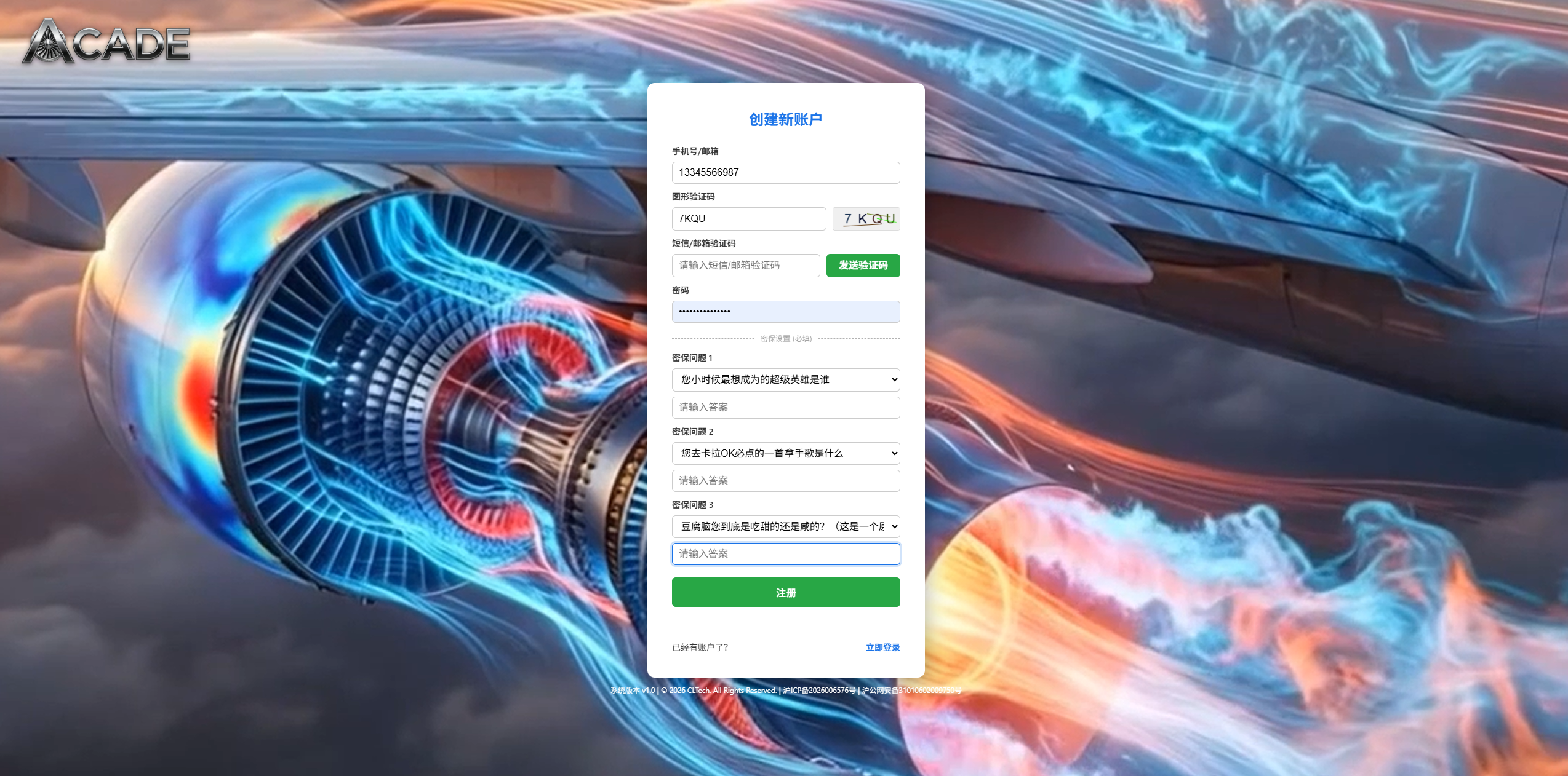
On the registration page, fill in the following fields:
| Field | Description |
|---|---|
| Phone Number/Email | China mainland phone number (11 digits) or international email (Gmail, Outlook, Hotmail, Yahoo supported) |
| Password | Set your login password |
| Captcha | Enter the captcha shown on the right (click to refresh) |
| SMS/Email Code | Click "Send Code" to receive a 6-digit verification code by phone or email |
| Security Questions 1~3 | Select from preset questions or create custom ones, and fill in the answers (used for password recovery) |
Registration Restrictions
- Phone number registration is only available from China mainland IP addresses; overseas users must register with an email address
- Maximum 3 accounts per IP address
- You must check "I have read and agree to the Privacy Policy and Terms of Service" before submitting
Click "Register" when done. You will be automatically redirected to the login page upon success.
2. Log In
Enter your phone number/email and password on the login page, check the agreement checkbox, and click "Login".
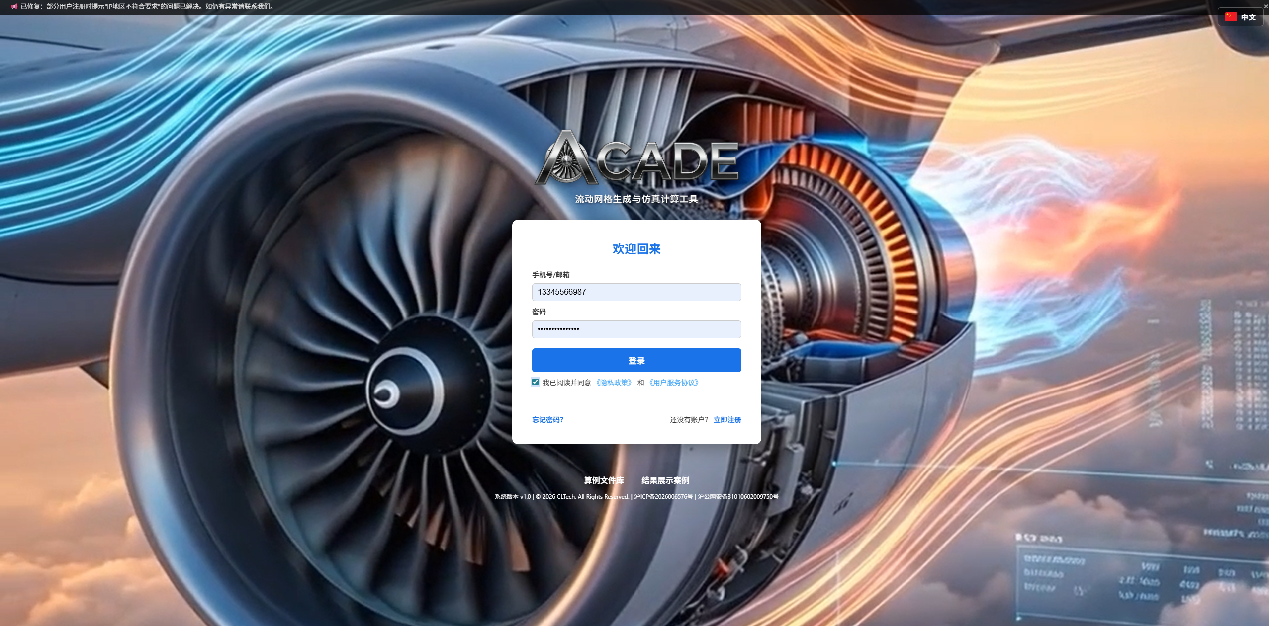
You will be automatically redirected to the Task Center after a successful login.
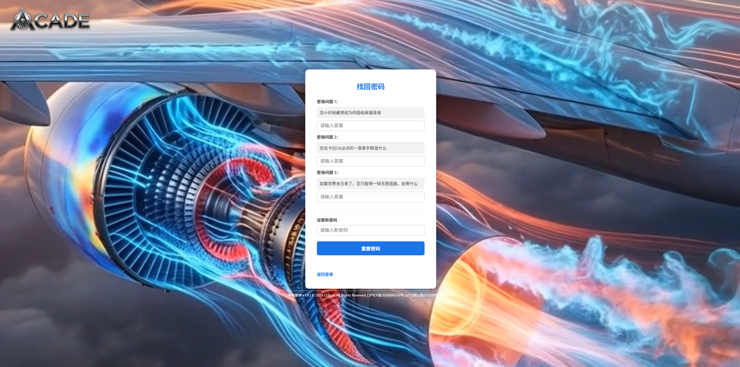
3. Reset Password
If you forget your password, click the "Forgot password?" link on the login page.
Step 1: Enter the phone number/email used during registration and click "Next".
Step 2: The system displays your 3 security questions. Answer each one, set a new password, and submit.
4. Task Center Overview
After logging in, the Task Center page is organized from top to bottom as follows:
- User Info Bar — Shows the logged-in account name and a logout button
- Task History Table — Lists all submitted tasks and their statuses
- Create New Task Area — For configuring and submitting new computation tasks
- Utility Tools — AI Assistant and Feedback buttons in the bottom-right corner
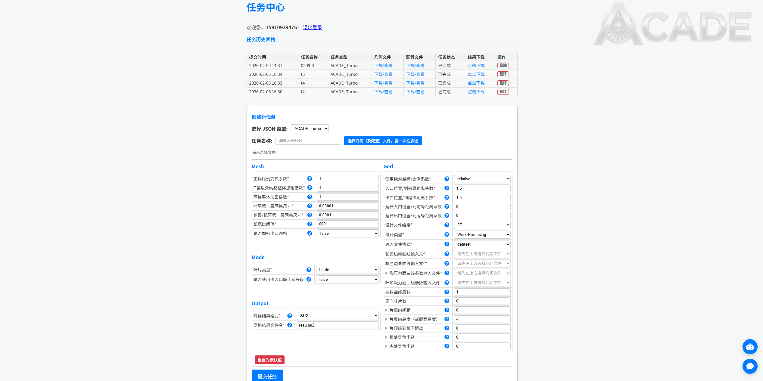
4.1 Task History Table
Column descriptions:
| Column | Description |
|---|---|
| Submit Time | Date and time the task was submitted |
| Task Name | The custom name you assigned to the task |
| Task Type | ACADE_Turbo / ACADE / SU2 |
| Geometry File | Uploaded geometry file (click to download) |
| Config File | Auto-generated JSON configuration (click to download) |
| Status | Pending → Processing → Completed / Failed |
| Result Download | Available for download after task completion |
| Actions | Cancel (Pending tasks only) / Delete |
The table refreshes automatically every 45 seconds.
5. Create a New Task
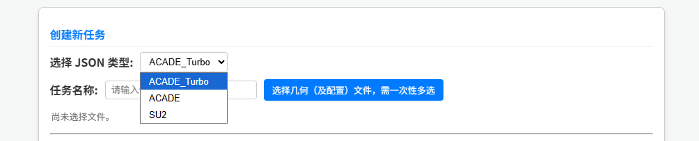
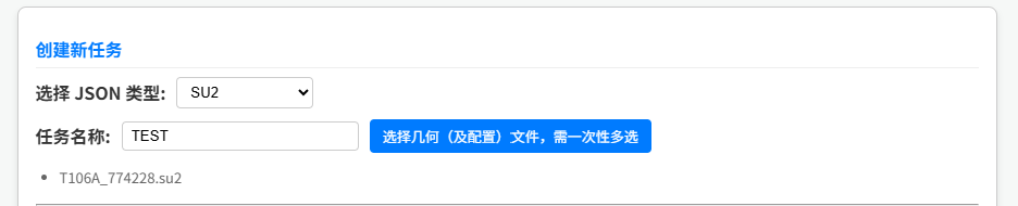
5.1 Select Task Type
In the "Create New Task" area, first select the task type from the dropdown:
| Type | Description | Status |
|---|---|---|
| ACADE_Turbo | Turbomachinery structured mesh generation | ✅ Available |
| ACADE | Aircraft external flow field with boundary layer mesh adaptation | ⚠️ Not yet available |
| SU2 | CFD simulation | ✅ Available |
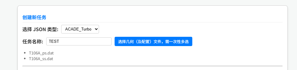
5.2 Enter Task Name
Enter a name for this task in the "Task Name" field to help identify it in the history table.
5.3 Select Files
Click "Select geometry (or mesh) files, multi-select required" and select all required files at once in the file picker dialog.
File Format Requirements
Allowed file formats differ by task type:
- ACADE_Turbo:
.dat,.csv,.curve,.geomTurbo - SU2:
.su2,.dat,.csv
If an unsupported file format is selected, the system will show an alert and clear the selection.
After a successful selection, the file list is displayed below the button:
6. ACADE_Turbo Parameter Configuration
After selecting ACADE_Turbo, the parameter form loads automatically. Parameters are grouped into the following sections:
6.1 Mesh
| Parameter | Description | Default |
|---|---|---|
| Coordinate Scale Factor | All xyz coordinates in the output file are multiplied by this factor. Default unit is meters. | 1.0 |
| Non-O Grid Coarsening Factor | Grid coarsening factor, should be between 1 and 2 | 1.0 |
| Grid Refinement Factor | Grid refinement factor, should be greater than 1 | 1.0 |
| Blade Wall First Layer Size | First layer mesh size on blade wall | 1e-5 |
| Hub/Shroud First Layer Size | First layer mesh size on hub/shroud wall | 1e-5 |
| Aspect Ratio Threshold | Maximum mesh aspect ratio | 2000 |
| Refine Outlet Mesh | Whether to refine the outlet mesh | false |
6.2 Mode
| Parameter | Description | Options |
|---|---|---|
| Blade Type | "blade" for smooth transition blades; "wing" for sharp trailing edge blades | blade / wing |
| Use Inlet/Outlet Extension | Can be used in 3D rotating cases to create stationary extension sections | true / false |
6.3 Gerl
| Parameter | Description |
|---|---|
| Use Absolute/Relative Mode | Select "absolute" to use z-coordinate values; select "relative" to use ratio coefficients |
| Inlet Position | (Rotating) Inlet start coordinate, or extend from leading edge by this factor × axial chord length |
| Outlet Position | (Rotating) Outlet end coordinate, or extend from trailing edge by this factor × axial chord length |
| Extended Inlet Position | Extended inlet z-coordinate, or extend from inlet position by this factor × axial chord. Effective when using inlet/outlet extension. |
| Extended Outlet Position | Extended outlet z-coordinate, or extend from outlet position by this factor × axial chord. Effective when using inlet/outlet extension. |
| Design File Dimension | Blade geometry coordinate points are 2D or 3D. Note: 2D currently only supports .dat format. |
| Design Type | Work-Absorbing family: Compressor, Pump, Fan, Blower; Work-Producing family: Gas Turbine, Steam Turbine, Hydraulic Turbine, Wind Turbine, Stator/Diffuser/Nozzle Guide Vane |
| Input File Format | Note: 2D currently only supports dataset format. Other options will be processed as dataset. |
| Pressure Side Curve File | For geomTurbo or curve format, fill here. For data type, select pressure and suction side files separately. For dataset, select the first blade curve file with the smallest index number. |
| Suction Side Curve File | Required when format is dataset or IGGdata |
| Hub Boundary Curve File | Hub endwall boundary curve file (if applicable) |
| Shroud Boundary Curve File | Shroud endwall boundary curve file (if applicable). Must be paired with the hub file. |
| Number of Curve Layers | For dataset format, this must be filled accurately to read all layer files by filename |
| Number of Blades | Must be filled accurately when blades are arranged in axial periodicity |
| Blade Pitch | Must be filled accurately when the blade is a 3D extrusion of a 2D design file |
| Blade Span (or Section Height) | Must be filled for 3D extrusion from 2D design. For 3D design input, enter a value between 0 and 1 to generate a 2D mesh at that relative span height; keep default -1 to generate a 3D passage mesh |
| Tip Gap Distance | Gap size between blade tip and shroud. Fill 0 for no gap. |
| Hub Fillet Radius | Hub fillet radius |
| Tip Fillet Radius | Tip fillet radius, only available when there is no tip gap |
6.4 Output
| Parameter | Description | Options |
|---|---|---|
| Mesh Output Format | Output mesh file format | ANSYSmsh / SU2 |
| Mesh Output Filename | Output filename, must include file extension | — |
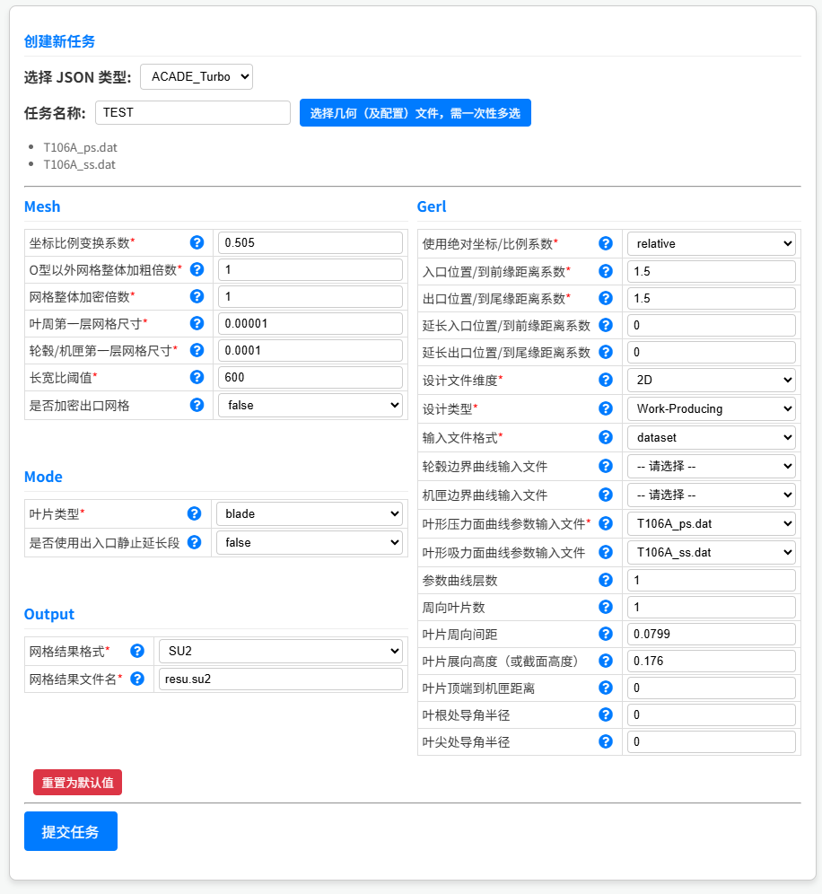
Parameter Tips
Parameters with a ? icon show detailed descriptions on hover. Parameters marked with a red * are required.
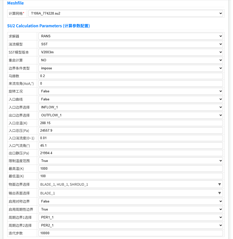
7. SU2 Simulation Parameter Configuration
After selecting SU2, the parameter form is divided into three main sections:
7.1 Mesh
Select the .su2 mesh file from the uploaded files. The system will automatically parse the boundary markers contained in the mesh, which will be available for boundary condition configuration below.
7.2 SU2 Calculation Parameters
This is the core configuration area for SU2 tasks, containing the following sub-sections:
Solver and Turbulence Model
| Parameter | Description |
|---|---|
| Solver | Select the solver type |
| Turbulence Model | Select the turbulence model |
| SST Model Version | Version options when SST turbulence model is selected |
| Restart Calculation | Whether to restart from an existing result file |
| Restart File | The .dat result file used for restart calculation |
Boundary Conditions
Two boundary condition types are supported:
Farfield Boundary Condition: For external flow problems.
| Parameter | Description | Range |
|---|---|---|
| Mach Number | Freestream Mach number | 0 < Ma < 2.0 |
| Angle of Attack (AoA) | Angle of attack in degrees | 0 ≤ AoA < 90 |
| Sideslip Angle (β) | Sideslip angle in degrees | 0 ≤ β < 90 |
| Freestream Pressure | Freestream static pressure (Pa) | 0 < P < 1013250 |
| Freestream Temperature | Freestream static temperature (K) | 273 < T < 1000 |
| Freestream Turbulence Intensity | Freestream turbulence intensity | 0~1 |
| Farfield Boundary Selection | Select farfield marker from mesh boundaries | — |
Inlet/Outlet Boundary Condition: For internal flow problems (e.g. turbomachinery).
| Parameter | Description | Range |
|---|---|---|
| Inlet Total Temperature | Inlet total temperature (K) | 273 < T < 1000 |
| Inlet Total Pressure | Inlet total pressure (Pa) | 0 < P < 1013250 |
| Inlet Turbulence Intensity | Inlet turbulence intensity | 0~1 |
| Inlet Flow Angle | Inlet flow angle in degrees | 0 ≤ α < 90 |
| Outlet Static Pressure | Outlet static pressure (Pa) | 0 < P < 1013250 |
| Inlet Boundary Selection | Select inlet marker from mesh boundaries | — |
| Outlet Boundary Selection | Select outlet marker from mesh boundaries | — |
Rotating Case (Turbomachinery)
| Parameter | Description |
|---|---|
| Rotating Case | Whether to enable rotation |
| Axial Velocity (m/s) | Inlet axial velocity |
| Rotation Speed (RPM) | Rotor rotation speed |
| Machine Type | Turbomachinery machine type |
| Enable Shroud Boundary | Whether to define shroud surface separately |
| Inlet/Outlet NRBC | Whether to enable Non-Reflecting Boundary Conditions |
Wall and Other Boundaries
| Parameter | Description |
|---|---|
| Wall Boundary Selection | Select all solid wall boundaries |
| Output Surface Selection | Select surfaces for data output (must be a subset of wall boundaries) |
| Enable Symmetry Boundary | Whether to use a symmetry plane |
| Symmetry Boundary Selection | Select symmetry marker |
| Enable Periodic Boundary | Whether to use periodic boundaries |
| Periodic Boundary 1/2 Selection | Select the two paired periodic boundaries |
Solver Control
| Parameter | Description | Range |
|---|---|---|
| Limit Temperature Range | Whether to limit the computation temperature range | true / false |
| Max Temperature (K) | Upper temperature limit | 0 < T ≤ 10000 |
| Min Temperature (K) | Lower temperature limit | 0 < T < Max Temperature |
| Iteration Count | Total number of iterations | 100 ≤ N ≤ 200000 (integer) |
7.3 Post Processing
| Parameter | Description |
|---|---|
| Slice Position 1 (m) | Post-processing analysis cross-section position 1 |
| Slice Position 2 (m) | Post-processing analysis cross-section position 2 |
| Inlet Analysis Position 1 (m) | Data collection position upstream of inlet |
| Outlet Analysis Position 2 (m) | Data collection position downstream of outlet |
| Mach Number Sampling Height | Span ratio position for Mach number sampling (0~1) |
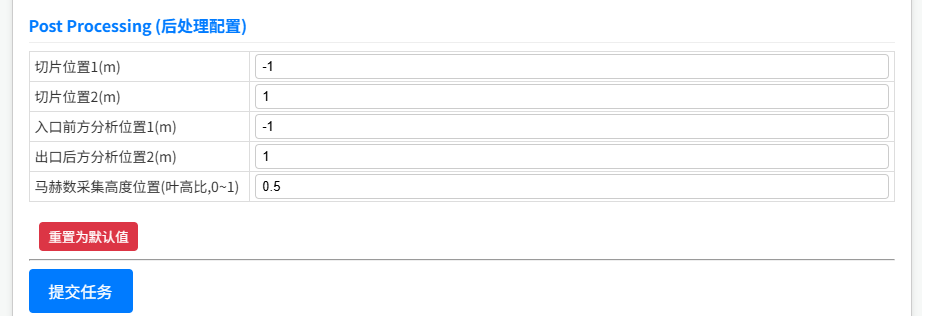
8. Submit a Task
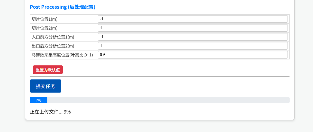
After completing all parameter configuration, click the "Submit Task" button at the bottom of the page.
The upload progress bar is shown during submission:
- Upload Phase — Files are uploaded to the server, progress bar shows 0%~80%
- Processing Phase — Server receives and validates files, progress bar advances slowly from 80% to 95%
- Complete — On success, the progress bar turns green at 100% and the page refreshes automatically after 2 seconds
Before Submitting
- Parameters marked with a red * are required
- If there are validation errors, the affected input fields will show a red border with an error message — fix all errors before resubmitting
- Each account has a task limit; delete old tasks before submitting new ones if the limit is reached
9. View and Manage Tasks
9.1 Task Status Reference
| Status | Meaning |
|---|---|
| Uploading | Files are being uploaded |
| Pending | Task submitted, waiting in queue |
| Processing | Server is running the computation |
| Completed | Computation finished, result available for download |
| Failed | Computation failed; check parameters or contact support |
| Cancelled | Cancelled by the user |
9.2 Download Results
Once the task status shows "Completed", click "Download" in the Result Download column to get the output file.
9.3 Cancel a Task
Only tasks in "Pending" status can be cancelled. Click the "Cancel" button in the Actions column and confirm.
9.4 Delete a Task
Tasks in any status can be deleted. Click the "Delete" button in the Actions column and confirm.
Warning
Deletion is permanent and cannot be undone. The geometry file, configuration file, and result file will all be permanently removed.
10. Utility Features
10.1 AI Assistant
Click the AI Assistant button (blue circular icon) in the bottom-right corner of the page to open the chat window.
The AI Assistant specializes in turbomachinery and flow simulation, and can:
- Answer parameter configuration questions
- Provide mesh generation advice
- Help analyze computation results
- Accept uploaded images for visual analysis
- Search the web for the latest references
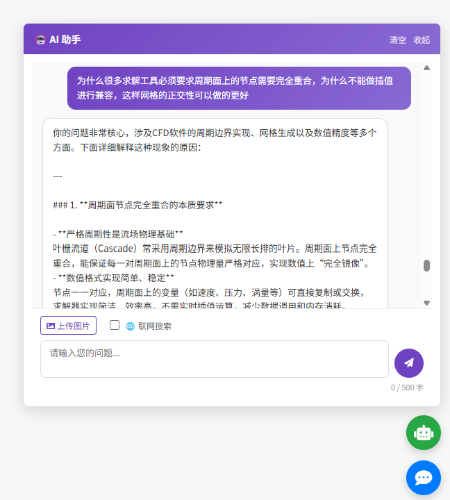
AI Assistant Usage Limits
- Maximum 500 characters per input
- Uploaded images must not exceed 5MB
- Daily conversation count is limited
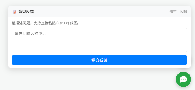
10.2 Feedback
Click the Feedback button (speech bubble icon) in the bottom-right corner to submit an issue report.
Supports:
- Text description of the issue
- Direct paste (Ctrl+V) of screenshots
- Multiple image preview and removal
10.3 Language Switch
- Login / Register / Reset Password pages: Click the language button (中 / EN) in the top-right corner to switch
- Task Center page: Interface language follows the setting from the login page
11. Frequently Asked Questions
Q: Registration says "IP region not allowed"?
A: Phone number registration is only available from China mainland IP addresses. If you are using a VPN or proxy, please disable it and try again. Overseas users can register with an email address instead. This issue has also been fixed recently — if it still occurs, please contact us via the Feedback button.
Q: Task stays in "Pending" status for a long time?
A: Tasks are processed in submission order. During peak hours there may be a wait. The table refreshes every 45 seconds automatically; you can also refresh the page manually to check the latest status.
Q: Task status shows "Failed". What should I do?
A: Please check the following:
- Whether the uploaded geometry file format is correct
- Whether the parameter configuration is valid (especially required fields)
- Whether the file content is complete and not corrupted
If everything looks correct and the task still fails, please submit a report via the Feedback button in the bottom-right corner.
Q: When will the ACADE module be available?
A: The ACADE module (aircraft external flow field with boundary layer mesh adaptation) is currently in internal testing. Please stay tuned for announcements.